
What Is a Liquid Cooling Energy Storage System and How Does Its Thermal Loop Work?
May 26, 2026 / Battery Expert Team / battery energy storage
Introduction
With the exponential acceleration of Commercial and Industrial Energy Storage Systems (C&I ESS) alongside massive utility-scale installations globally, standard air-cooled architectures are hitting severe physical bottlenecks. Modern project demands require unprecedented volumetric capacity, safe operation under extreme environmental thermal stress, extended operational lifespan, and ironclad mitigation of catastrophic thermal events. Consequently, the implementation of a Liquid Cooling Energy Storage System has transitioned from an advanced engineering alternative into the dominant, industry-standard technology pathway for high-capacity power networks. Particularly across intensive application verticals—including integrated solar-storage-charging infrastructure, grid-scale substations, mission-critical data centers, localized microgrids, and high-power EV charging infrastructure—the liquid-cooled battery energy storage system (BESS) is rapidly replacing traditional forced-air ventilation options due to its clear thermodynamic superiority.
This comprehensive architectural guide provides an exhaustive engineering analysis of contemporary liquid cooling design parameters. We break down the underlying fluid mechanics, examine multi-tier component integration, evaluate empirical performance data against air-cooled alternatives, and analyze long-term operational and maintenance (O&M) protocols. Whether you are an infrastructure procurement officer, an engineering, procurement, and construction (EPC) partner, or an asset manager looking to select the ideal hardware framework for a future-proof utility project, understanding these advanced thermal mechanics is essential to securing asset longevity and maximizing project return on investment (ROI).
What Is a Liquid Cooling Energy Storage System?
Liquid Cooling Energy Storage System Definition
An industrial-grade Liquid Cooling Energy Storage System represents a highly engineered, self-contained electrochemical energy storage apparatus that utilizes closed-loop liquid circulation to manage cell-level thermodynamic profiles. Unlike traditional installations that rely on ambient air or industrial HVAC blowers to move heat convective-wise, a liquid-cooled setup directly couples cells to liquid channels. The primary operational objectives of an integrated fluid-based system include the precise maintenance of internal cell temperatures within narrow optimal operational bands, the reduction of cross-pack cell-to-cell temperature differentials, the minimization of auxiliary parasitic energy losses, and the structural prevention of progressive thermal runaway propagation. By leveraging the superior heat capacity of liquid mediums, these systems achieve unparalleled heat dissipation, enabling high-density configurations that would be fundamentally unsafe under standard air-cooled operating restrictions.
How a Liquid Cooling Energy Storage System Works
The functional mechanics of an advanced liquid-jacketed thermal management loop rely on continuous, precision-controlled heat transfer. A high-efficiency liquid cooling plate, typically fabricated from high-thermal-conductivity aluminum alloys, is physically embedded directly beneath or sandwiched between individual lithium iron phosphate (LFP) cell clusters. An eco-friendly, non-corrosive glycol-water mixture or specialized dielectric fluid is propelled through a closed coolant pipeline by an industrial-grade, variable-speed circulation pump. As the battery array experiences high C-rate charging or discharging cycles, the metabolic heat generated via internal cell resistance is rapidly absorbed by the liquid cooling plate through conductive thermal coupling.
The warmed coolant is then driven out of the battery module rack into a central heat exchanger or chiller unit equipped with automated electronic expansion valves. Here, the heat is transferred out of the internal closed loop and rejected into the outside atmosphere. Conversely, during extreme cold-weather operations, the system can engage an inline electric block heater within the coolant loop to pre-heat the cells, safely bringing them above freezing to prevent lithium plating during fast-charging sequences. This bidirectional thermal control is governed autonomously by real-time telemetry cross-referenced across hundreds of individual thermal sensors.
💡 Featured Snippet: What is a liquid cooling energy storage system?
A liquid cooling energy storage system is a battery energy storage solution that uses circulating coolant to control battery temperature. Compared with air cooling systems, liquid cooling provides higher thermal efficiency, better temperature uniformity, improved battery safety, and longer battery lifespan.
Liquid Cooling vs Air Cooling Energy Storage System
Why Forced-Air Ventilation Is Reaching Its Technological Limits
Traditional forced-air cooling designs rely on shifting massive volumes of air through complex structural air ducts to strip heat from cell surfaces via convection. While historically cost-effective for small-scale residential setups, this paradigm fails significantly under the rigorous duty cycles demanded by modern commercial battery storage system frameworks. Air possesses a very low specific heat capacity (approximately 1.005 kJ/kg·K), meaning huge volumes of gas must be pushed continuously to achieve meaningful thermal energy rejection.
This creates substantial localized temperature gradients; cells located closest to the cold air intake are chilled effectively, while cells near the rear exhaust accumulate residual heat, resulting in severe cross-pack temperature deviations often exceeding 5°C to 8°C. In high-ambient environments like Southeast Asia, the Middle East, Africa, and the southern United States, this structural imbalance accelerates the degradation of the warmer cells, causing localized capacity fade, severe internal resistance mismatches, and a rapid drop in overall system State of Health (SOH). Furthermore, forced-air networks require complex internal dust filtration, large physical footprints for air channels, and high acoustic profiles that restrict deployment near urban population centers.
The Core Architectural Advantages of Liquid-Cooled BESS Units
Transitioning to an advanced Liquid Cooling Energy Storage System solves these physical constraints through precise fluid mechanics. Water-glycol solutions feature a specific heat capacity that is roughly four times higher than air, alongside thermal conductivity metrics that exceed air by more than twenty times. This allows for highly localized, efficient thermal management within an extremely compact footprint. Let us break down the exact performance advantages verified across the industry:
- High-Efficiency Thermal Management: Liquids absorb high-flux thermal energy instantly during intensive 1C or 2C charge/discharge profiles, capping the absolute max temperature of the cells well within safe limits.
- Better Battery Temperature Control: Premium liquid configurations maintain cell-to-cell temperature deltas to an ultra-narrow margin of ≤2°C across the entire containerized architecture. This uniformity guarantees balanced aging profiles and prevents premature string capacity loss.
- Improved Battery Safety: By eliminating hot spots and maintaining continuous battery temperature control, the system curtails the primary mechanism of cell degradation and thermal runaway initiation. If a localized cell failure does occur, the cooling fluid acts as a firebreak, absorbing excess energy to prevent cascading propagation to adjacent racks.
- Compact Design and High Energy Density Storage: Because liquid channels require fractions of the physical space demanded by bulky air ducts, manufacturers can pack cells tightly. This enables high energy density storage configurations, frequently saving up to 35% to 40% of real estate footprint compared to air-cooled models.
- Low Noise Operation: Swapping loud, high-RPM industrial air blowers for optimized liquid circulation pumps and variable-frequency fans reduces the acoustic emission profile drastically, making the system ideal for sensitive environments like hospitals, commercial business parks, and urban microgrids.
- High Architectural Compatibility: These systems feature universal plug-and-play synchronization with hybrid power conversion system (PCS) units, advanced energy management system (EMS) platforms, localized solar arrays, and high-capacity EV charging infrastructure.
Technical Benchmarking Matrix: Liquid vs. Air Thermal Systems
The following structural parameters highlight empirical performance data derived from the BloombergNEF (BNEF) 2025 Global Energy Storage Technology Outlook and recent 2026 international utility field evaluations:
| Engineering Parameter | Traditional Forced-Air BESS | Liquid Cooling BESS Solution |
|---|---|---|
| Heat Transfer Coefficient | ~20 – 100 W/m²·K | ~1,000 – 4,000 W/m²·K |
| Cell-to-Cell Temp Delta (ΔT) | > 5°C to 8°C (Highly Variable) | ≤ 2°C (Ultra-Uniform) |
| System Energy Density (MWh/Container) | Approx. 2.5 MWh to 3.4 MWh | Up to 5.0 MWh – 6.8 MWh |
| Parasitic Auxiliary Power Draw | 7% – 12% of total throughput | 3% – 5% (Using Variable Speed Pumps) |
| Expected Lifespan to 80% SOH | ~4,000 – 5,000 Cycles | 6,000 – 8,000+ Cycles |
💡 Featured Snippet: Why is liquid cooling better than air cooling in energy storage systems?
Liquid cooling provides faster heat dissipation, better temperature uniformity, lower battery degradation, higher safety, and improved energy efficiency compared with traditional air cooling systems.
Liquid Cooling Energy Storage System Structure Explained
An industrial or utility-scale liquid-cooled energy infrastructure system is not merely an assortment of individual components; it is a highly integrated, multi-layered technological stack where hardware layers and control software communicate seamlessly in real time.
1. The Electrochemical Battery System
The physical foundation of the system relies on high-grade LFP lithium battery chemistry packed into solid structural configurations. Individual battery cells are balanced electronically and compressed into a rigid Battery PACK module. These PACKs are stacked vertically inside heavy-duty industrial iron enclosures to form a standardized Battery Rack. Every single cell profile is design-mapped to align flush with the integrated liquid cooling plate layer to minimize interface thermal resistance.
2. Power Conversion System (PCS)
The PCS acts as the bidirectional power gatekeeper of the installation, executing seamless AC/DC and DC/AC power transitions. During charging cycles, the PCS draws alternating current from the localized grid or photovoltaic network and converts it into stable direct current to charge the battery banks. Conversely, during discharge triggers, it outputs synchronized AC power matching grid harmonic and voltage metrics. Advanced liquid-cooled setups often incorporate shared liquid cooling loops that service both the high-frequency IGBT switches within the PCS and the electrochemical cells simultaneously.
3. Multi-Tier Battery Management System (BMS)
The BMS acts as the underlying safety computing layer. Operating across a multi-tiered hierarchy (comprising slave cell controllers, master pack controllers, and system-level rack units), the BMS executes microsecond-level telemetry scans monitoring cell voltage profiles, localized thermal variations, internal resistance growth, and absolute State of Charge (SOC) tracking. If the BMS registers an anomalous thermal surge, it sends an instantaneous priority command to the thermal management system to maximize fluid flow velocity or isolates the compromised string via solid-state contactors before structural damage manifests.
4. Energy Management System (EMS)
The EMS represents the macroscopic software brain directing economic and functional routing. By tracking external parameters—such as real-time regional utility pricing feeds, localized building load curves, and meteorological forecasting models—the EMS autonomously commands the entire asset to run optimized financial protocols. It calculates when to store cheap electrons, when to execute local facility demand charge reduction, when to participate in regional frequency response markets, and how to balance microgrid distributions.
5. Closed-Loop Liquid Thermal Management System
This core thermal system layer isolates and addresses heat accumulation across the entire physical structure. It incorporates a specialized liquid cooling plate network running directly beneath cell matrices, specialized reinforced coolant pipelines outfitted with leak-detection sensor loops, an industrial variable-frequency circulation pump, an integrated multi-stage heat exchanger/chiller unit, and digital temperature sensors embedded into both fluid inlets and outlets to adjust coolant flow dynamically.
Applications of Liquid Cooling Energy Storage Systems
The superior thermodynamic capabilities of a modern liquid cooling setup make it uniquely suited for heavy-duty, high-throughput energy infrastructure projects across the globe.
Utility-Scale BESS Installations
On the main transmission and distribution grid level, a utility scale liquid cooling battery storage system is vital to executing fast grid frequency regulation, automated black-start protocols, and massive bulk load shifting. Because grid networks frequently demand instantaneous high-MW power injections to counteract sudden drops in regional generation, cells are subjected to intense current stresses. Liquid-cooled containers handle these high C-rate bursts smoothly without exceeding structural temperature boundaries, ensuring that utility companies preserve grid stability without sacrificing multi-million dollar battery assets to accelerated thermal degradation.
Large-Scale Solar & Wind Farms
Renewable generation assets suffer from inherent curtailment and intermittency problems. Co-locating a containerized liquid cooled battery energy storage system allows wind and solar asset operators to smooth out volatile generation profiles, store massive daytime or nighttime over-generation, and dispatch clean electricity during peak high-value pricing windows. The superior cooling efficiency ensures that these outdoor arrays operate at maximum capacity even when exposed to direct solar radiation on vast desert solar fields or high-humidity coastal wind sites.
Mission-Critical Data Centers
Modern AI-driven hyperscale data centers operate with highly intensive base loads and zero tolerance for power interruptions. Implementing an industrial liquid cooling BESS solution within a data center environment delivers clean, uninterruptible power supply (UPS) backup while fitting comfortably inside restricted indoor spaces due to its compact structural design. Additionally, the low noise and lack of vibration ensure that sensitive server arrays run completely undisturbed.
High-Power EV Charging Infrastructure
As heavy-duty electric logistics fleets deploy across transit corridors, highway charging hubs are adding high-amperage 350kW+ DC fast hyper-chargers that cause severe, localized demand spikes on the utility grid. Integrating an outdoor liquid cooled battery cabinet right at the charging plaza creates a critical power buffer. The battery charges slowly from the localized grid or on-site solar awnings during low-demand gaps, and then discharges high-amperage current instantaneously into vehicles during active charging sessions, shielding operators from massive demand penalty charges and avoiding costly substation upgrades.
Commercial & Industrial (C&I) Facilities
For modern manufacturing factories, steel foundries, and chemical processing facilities, an integrated commercial liquid cooling energy storage system delivers tangible operational savings. Managed through an automated EMS, the installation executes highly effective demand charge reduction protocols and automatic peak-to-valley price arbitrage, storing cheap energy during off-peak night cycles and feeding it back to the factory floors when commercial electricity rates spike.
Transportation, Operation and Maintenance of Liquid Cooling ESS
Transportation Considerations for Liquid-Cooled Enclosures
Logistical planning for high-capacity liquid-cooled systems requires rigorous safety engineering. Because these units are shipped with dense battery modules already integrated alongside liquid networks, containers must feature advanced structural anti-shock and vibration damping. High-quality enclosures conform to strict UN38.3 and international freight shipping standards. To prevent internal moisture problems or fluid freeze-ups during maritime transit through changing climate zones, manufacturers typically ship the systems with internal coolant systems drained or utilize stabilized pre-mixed fluids that feature deep sub-zero thermal resilience. Advanced structural designs carry up to an IP65 or IP66 environmental ingress protection rating to ensure external elements never compromise internal electronic control layers.
Mitigating Operational Risks and Fluid Leakage
The primary risk associated with any fluid-based electrical system is the potential for coolant leakage. To mitigate this concern, reputable liquid cooled energy storage system manufacturer entities implement strict multi-layered safety mechanisms. Multi-point pressure monitoring sensors are placed at the fluid pumps to detect even fractional pressure drops that indicate a structural micro-leak.
Furthermore, coolant pipelines are engineered completely exterior to the electric terminal boundaries, or utilize advanced micro-groove physical connections that isolate fluid flow channels completely from cell contacts. Automated safety logic ensures that if an internal moisture or conductivity sensor is triggered, an automatic isolation valve instantly cuts off fluid flow to the affected rack segment, preventing electrical shorting while adjacent battery strings continue to operate safely.
Long-Term O&M Protocols and Cost Reductions
Counter to early industry assumptions, the ongoing maintenance requirements of a liquid-cooled BESS are frequently lower and highly streamlined compared to air-cooled models. Traditional air systems require maintenance teams to clean or swap out massive dust and air filters every few months to prevent fan clogging and performance drop-offs. Liquid networks, being completely sealed from the outside environment, avoid internal particulate accumulation entirely. Standard maintenance cycles occur once every 12 to 24 months, focusing primarily on assessing coolant fluid levels, testing pH and anti-corrosive additive concentration metrics, checking pump motor efficiency, and inspecting pipeline gaskets.
Furthermore, modern energy storage thermal management platforms feature advanced cloud-based remote O&M software. These systems run continuous predictive maintenance algorithms that can isolate a flagging pump motor or identify a slight thermal anomaly well before hardware failure occurs, minimizing manual technician dispatches and lowering lifetime operational overhead.
How Liquid Cooling Improves Energy Storage Cooling Efficiency
Maximizing Heat Exchange Dynamics
The foundational secret behind the high performance of a liquid cooling asset traces directly back to raw thermodynamics. The rate of heat rejection across an interface is governed by the standard heat transfer relation:
Where Q represents total heat transfer rate, h is the convective heat transfer coefficient, A is the effective surface contact area, and ΔT is the temperature delta. Because a liquid fluid path delivers a convective coefficient (h) that is orders of magnitude superior to air, the heat removal is near-instantaneous. This eliminates localized thermal hot spots, ensuring stable internal cell resistance and preserving overall charging efficiency even under maximum load cycles.
Slashing Parasitic Energy Draw
In older forced-air BESS installations, keeping battery cells cool in mid-summer requires running multiple massive industrial air-conditioner compressors and high-wattage exhaust fans continuously. This represents a heavy parasitic energy load, frequently devouring up to 10% to 12% of the entire electrical energy stored within the battery system. Liquid-cooled systems utilize highly targeted fluid distribution channels and variable-frequency smart pumps that draw minimal power. In optimized deployments, incorporating advanced HVAC free cooling technology allows the system to bypass the chiller entirely during cooler night cycles, leveraging ambient external temperatures to cool the fluid loop naturally. This drops auxiliary parasitic energy consumption down to a lean 3% to 5%, boosting the net Round-Trip Efficiency (RTE) of the entire asset.
Extending Cell Lifetime Yield and Levelized Cost of Storage (LCOS)
Battery cell degradation accelerates exponentially when exposed to sustained operating temperatures above 35°C or when subjected to asymmetric internal temperature deltas. By stabilizing cell environments to an ultra-uniform, comfortable 25°C baseline year-round, liquid thermal management system engineering effectively halves the rate of nominal capacity loss and internal resistance growth. This extends the field service lifespan from a basic 4,000 cycles up to 8,000+ full operational cycles before the system hits standard end-of-life parameters. Over a typical 15-to-20-year project finance window, this extended life cycle significantly lowers the Levelized Cost of Storage (LCOS) per megawatt-hour, accelerating your capital payback timeline and maximizing your net system ROI.
💡 Featured Snippet: How does liquid cooling improve battery energy storage efficiency?
Liquid cooling improves energy storage efficiency by removing heat faster, maintaining uniform battery temperatures, reducing auxiliary power consumption, and extending battery lifespan.
Deep Technical Deep-Dive: Battery Chemistries & Industrial Alternatives
To assist procurement teams with evaluating prospective solutions, it is critical to break down the underlying electrochemical technologies and alternative thermal management frameworks present in the 2026 energy infrastructure market.
1. Lithium Iron Phosphate (LiFePO4 / LFP)
LFP represents the overwhelming benchmark for contemporary C&I and utility deployments. Featuring a robust crystalline olivine structural configuration, LFP cells deliver excellent chemical and thermal stability. Their chemical bonds are highly resistant to structural breakdown under extreme electrical stress, meaning they do not release oxygen gas even if pushed to structural failure points, making them highly secure against thermal runaway events. LFP delivers a remarkable round-trip efficiency (RTE) profile of 88% to 92% and exceptional cycle life metrics (6,000 to 8,000 full cycles), though they possess a lower volumetric energy density compared to automotive-grade NMC options.
2. Sodium-Ion (Na-Ion) Technology
An emerging industrial alternative gaining significant traction is Sodium-Ion technology. This framework swaps out relatively rare lithium raw materials for widely available sodium ions derived from common earth salt compounds. Sodium-ion cells deliver exceptional safety profiles, possess non-flammable internal properties, and maintain remarkable capacity retention metrics down to ultra-low cold environments (-20°C and below). However, sodium-ion technology carries a much lower nominal volumetric density and has an early cycle life curve typically capped at 3,000 to 4,500 cycles, making it a specialized option for niche environmental deployments.
3. Vanadium Redox Flow Batteries (VRFB)
For massive multi-megawatt long-duration energy storage installations requiring continuous dispatch over 6 to 12+ hours, Vanadium Redox Flow systems represent a robust alternative. VRFB systems store energy within large external plumbing tanks filled with liquid vanadium electrolyte solutions. Because the active chemical capacity is separate from the physical power stack, these systems suffer virtually zero capacity fade or degradation over 20 to 25+ years of continuous cycling, and they possess zero thermal runaway risks. The severe drawbacks of VRFB architectures are their massive physical footprint requirements, complex internal hydraulic pump maintenance, and an initial capital expenditure hurdle that dwarfs lithium-based alternatives.
💬 Community Insight: Can I build a DIY 100kWh battery array by myself?
On prominent renewable infrastructure engineering forums and solar technology sub-reddits, procurement coordinators and facility engineers frequently ask variations of this question: “Our company has skilled industrial maintenance electricians on site; can we reduce initial procurement expenses by purchasing raw LiFePO4 cells and assembling a custom 100kWh battery bank internally?”
From an industrial safety, legal risk, and engineering perspective, the definitive answer is absolutely not. While low-voltage DIY configurations are acceptable for simple residential off-grid setups or marine use, custom-assembling a high-voltage commercial system introduces severe liability concerns. Industrial storage networks operate at high DC link potentials spanning from 400V to well over 1000V. Working with high-voltage DC string setups requires specialized testing equipment; minor assembly defects can spark catastrophic arc-flash events or structural fires. Furthermore, major corporate insurance providers will void commercial property policies if a loss traces back to non-laboratory-certified assembly. Finally, to interconnect any asset to a national utility network, the total installation must possess strict type-test certifications (including CE markings, IEC 62619, and regional utility compliance metrics like VDE-AR-N 4110). Grid operators will flatly refuse connection to any non-certified, self-assembled equipment.
🛠️ Recommended Product Spotlight: Industrial Liquid Cooling BESS
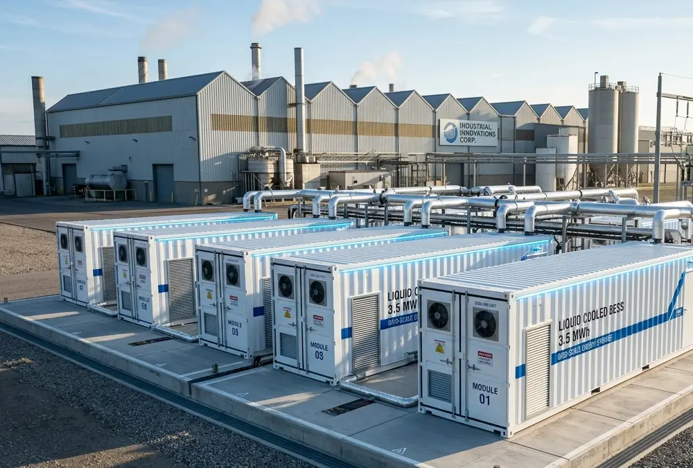
Hardware Classification: All-in-One Containerized Outdoor Liquid-Cooled BESS Enclosure
Technical Specifications: 500kW to 1MW Integrated Bidirectional PCS / 1.5MWh to 3.4MWh High-Density LiFePO4 Cell Configurations / Multi-Protocol Intelligent EMS Control Layer.
Engineering Assessment: This modular containerized layout represents the gold standard for high-throughput factory peak flattening, dynamic EV hyper-charging load stabilization, and localized commercial microgrids. The pre-packaged all-in-one configuration reduces physical engineering installation timelines by up to 60%, delivering verified multi-year cycle resilience under standard operations.
Why Liquid Cooling Energy Storage Systems Are Becoming the Industry Trend
The global energy landscape is undergoing a permanent structural realignment. As international carbon mandates tighten, industrial electricity grids face unprecedented stability pressures, and energy-intensive application spaces like hyperscale AI data centers expand rapidly, the need for dense, safe energy infrastructure is skyrocketing. This macroeconomic pressure is driving the rapid market transition away from historical ventilation frameworks toward fully integrated liquid-cooled systems.
According to comprehensive global sector transaction indicators published across international clean energy indexes, over 75% of new commercial and utility-scale procurement specifications actively mandate liquid thermal management loop architectures. By delivering lower Levelized Cost of Storage (LCOS), unmatched safety profiles, and minimal physical spatial requirements, liquid cooling technology has successfully secured its position as the definitive infrastructure trend for the next generation of renewable energy integration projects.
Conclusion
A modern Liquid Cooling Energy Storage System represents the absolute cutting edge of commercial and utility energy management technology. By offering superior thermal heat dissipation capabilities, uniform cell-to-cell temperature balancing, minimized parasitic energy draws, and a significantly compact deployment footprint, liquid-cooled setups consistently outperform outdated air-cooled configurations across every key operational metric.
For commercial infrastructure operators, industrial factories, and utility asset managers, choosing a premium liquid-jacketed configuration backed by robust EMS control software is a critical financial strategy that reduces long-term operational liabilities, extends battery cycling lifespans, and maximizes project return on investment. As international distribution networks become increasingly volatile, deploying a robust liquid-cooled energy asset ensures that your enterprise remains fully resilient, highly efficient, and deeply future-proof.
Related Posts
 https://anengjibattery.com/wp-content/uploads/2026/07/anengji-battery-4-12v-batteries-in-series-48v-battery-system.webp
675
1000
Battery Expert Team
https://anengjibattery.com/wp-content/uploads/2025/06/logo2-300x138.png
Battery Expert Team2026-07-25 14:44:422026-07-25 14:45:034 12V Batteries in Series: How to Build a 48V Power System
https://anengjibattery.com/wp-content/uploads/2026/07/anengji-battery-4-12v-batteries-in-series-48v-battery-system.webp
675
1000
Battery Expert Team
https://anengjibattery.com/wp-content/uploads/2025/06/logo2-300x138.png
Battery Expert Team2026-07-25 14:44:422026-07-25 14:45:034 12V Batteries in Series: How to Build a 48V Power System https://anengjibattery.com/wp-content/uploads/2026/07/anengji-battery-mah-battery-capacity-guide-industrial-applications.webp
800
800
Battery Expert Team
https://anengjibattery.com/wp-content/uploads/2025/06/logo2-300x138.png
Battery Expert Team2026-07-24 07:17:082026-07-24 07:17:27What Is mAh in Batteries? Complete Battery Capacity Guide
https://anengjibattery.com/wp-content/uploads/2026/07/anengji-battery-mah-battery-capacity-guide-industrial-applications.webp
800
800
Battery Expert Team
https://anengjibattery.com/wp-content/uploads/2025/06/logo2-300x138.png
Battery Expert Team2026-07-24 07:17:082026-07-24 07:17:27What Is mAh in Batteries? Complete Battery Capacity Guide https://anengjibattery.com/wp-content/uploads/2026/07/anengji-battery-do-lithium-batteries-freeze-cold-weather-fleet-performance.webp
672
800
Battery Expert Team
https://anengjibattery.com/wp-content/uploads/2025/06/logo2-300x138.png
Battery Expert Team2026-07-23 09:38:172026-07-24 09:51:33Do Lithium Batteries Freeze? How Low Temperatures Hurt Fleets
https://anengjibattery.com/wp-content/uploads/2026/07/anengji-battery-do-lithium-batteries-freeze-cold-weather-fleet-performance.webp
672
800
Battery Expert Team
https://anengjibattery.com/wp-content/uploads/2025/06/logo2-300x138.png
Battery Expert Team2026-07-23 09:38:172026-07-24 09:51:33Do Lithium Batteries Freeze? How Low Temperatures Hurt Fleets https://anengjibattery.com/wp-content/uploads/2026/07/anengji-battery-nicad-vs-lithium-ion-battery-architecture-comparison.webp
672
800
Battery Expert Team
https://anengjibattery.com/wp-content/uploads/2025/06/logo2-300x138.png
Battery Expert Team2026-07-22 08:03:562026-07-22 08:04:11NiCad vs Lithium Ion Batteries: Which Is Better for Industrial Use?
https://anengjibattery.com/wp-content/uploads/2026/07/anengji-battery-nicad-vs-lithium-ion-battery-architecture-comparison.webp
672
800
Battery Expert Team
https://anengjibattery.com/wp-content/uploads/2025/06/logo2-300x138.png
Battery Expert Team2026-07-22 08:03:562026-07-22 08:04:11NiCad vs Lithium Ion Batteries: Which Is Better for Industrial Use?


Leave a Reply
Want to join the discussion?Feel free to contribute!