
How Does a Lithium-Ion Battery Work and Stay Protected?
October 29, 2026 / Battery Expert Team / Battery Basics

Introduction
A lithium-ion battery can appear simple from the outside: connect a load and it supplies power; connect a charger and it stores energy again. Yet when a pack loses voltage under load, stops with charge still showing, or repeatedly interrupts charging, the usual one-line explanation—“lithium ions move between two electrodes”—is no longer enough.
In a forklift, AGV or storage system, those symptoms can mean a stopped shift, a missed charging window, repeated service calls or a battery replaced before the real fault is found. Understanding how the battery works helps separate normal electrochemical behaviour from a weak cell, high-resistance connection, incompatible charger, thermal limit or incorrect system setting.
To understand how a lithium ion battery works in real equipment, it helps to look at three levels: what happens inside one cell, how cells become a protected battery pack, and how that pack interacts with the charger and machine. This guide explains all three in plain English first, then adds the engineering detail needed by equipment buyers, fleet managers and integrators.
The short answer
During discharge, lithium ions move inside the cell through the electrolyte, while electrons travel through an external circuit and power the equipment. During charging, an external power source drives both flows in the opposite direction. A complete battery pack adds a BMS, fuse, switching devices, sensors, wiring, enclosure and thermal provisions so this process can happen within defined limits.
How Does a Lithium-Ion Battery Work in Simple Terms?
Think of a lithium-ion cell as having two coordinated paths. Lithium ions use an internal path through the electrolyte and separator. Electrons cannot pass through that separator, so they take the external path through the connected device. That external electron flow is what the motor, inverter or electronic load can use as electrical current.
The U.S. Department of Energy’s DOE Explains…Batteries describes batteries as devices that store energy in chemical-potential form. It also makes the two-path distinction: ions move through the electrolyte while electrons move through the external circuit. Charging raises the stored chemical potential; discharging converts part of it into usable electrical energy.
The two paths must operate together. If ions cannot move easily, or if the external electrical path has excessive resistance, the battery cannot deliver the expected power even when it still contains stored energy.
What Is Inside a Lithium-Ion Cell?
A cell is the smallest electrochemical unit that stores and releases energy. A battery may contain one cell or many cells connected together. According to UL Research Institutes’ lithium-ion battery explainer, the essential cell parts include two electrodes, an electrolyte, a separator and current collectors.
| Cell part | Plain-English role | Why it matters in a real battery |
|---|---|---|
| Anode | The negative electrode during discharge; commonly graphite in conventional lithium-ion cells. | It receives lithium during charging and releases lithium ions and electrons during discharge. |
| Cathode | The positive electrode during discharge. | Its material—such as LFP or NMC—strongly influences voltage, energy, power, thermal behaviour and cost. |
| Electrolyte | The medium that carries lithium ions between the electrodes. | Its transport properties and stability affect rate capability, temperature behaviour and safety. |
| Separator | A porous barrier that lets ions pass but keeps the electrodes apart. | Direct contact between the electrodes would create an internal short circuit rather than useful current through the load. |
| Current collectors | Conductive foils that connect electrode material to the cell terminals. | They provide the electronic path into and out of the cell and must handle current without excessive heating. |
Lithium is not normally moving around as pieces of metal in a rechargeable lithium-ion cell. It is stored within electrode structures. The University of Washington Clean Energy Institute explains lithium-ion intercalation as lithium ions being inserted into the layered structure of an electrode material. In simpler terms, the electrode acts like a host structure with places where lithium can enter and leave.
How a Lithium-Ion Battery Produces Power During Discharge
When the load is connected, lithium at the anode is released as lithium ions and electrons. The ions cross the electrolyte-soaked separator toward the cathode. The electrons cannot take that internal route, so they pass through the external circuit, perform work in the equipment and return at the cathode side.
Voltage is the electrical potential that pushes charge through the circuit. Current is the rate of charge flow. Energy is not the same as either one: battery energy is expressed in watt-hours or kilowatt-hours and is related to both voltage and capacity. This is why two batteries with the same amp-hour rating can store different amounts of energy if their voltages differ.
Why does voltage fall under load and recover afterward?
Suppose an operator starts a lift motor and the displayed pack voltage falls, then rises again when the motor stops. That does not automatically mean the battery has suddenly lost and regained energy. Every cell, cable, connector and busbar has resistance. As current rises, the measured terminal voltage falls below the relaxed open-circuit voltage.
Useful diagnostic relationship
Loaded voltage ≈ open-circuit voltage − (current × total resistance)
The important question is whether the drop is expected for the current or is being enlarged by a loose connection, undersized conductor, rising cell resistance or one weak cell. Record pack voltage at rest and under load, load current, minimum and maximum cell voltage, cell temperature and the voltage drop across major connections. Those measurements separate a normal response from a service problem.
An easily missed field detail: a BMS protects individual cells, not only the average pack voltage. One weak cell can reach its lower-voltage limit first and shut down the entire pack even when the average voltage still looks usable. Increasing amp-hours without identifying that cell-level trigger may not solve the problem.
How Charging Reverses the Process
Charging is not simply “putting electricity into a box.” The charger applies controlled electrical power that drives lithium ions from the cathode side back toward the anode while electrons return through the external charging circuit. Energy is stored again in chemical form.
A compatible charger must match the battery’s chemistry, series-cell count, permitted voltage window, current limit, temperature conditions, connector and—where required—communications. Charging time also depends on how much usable energy must be restored, charger output, conversion losses, temperature limits, current taper and balancing. Dividing amp-hours by charger amps is only a rough starting estimate, not a guaranteed charge time.
Many lithium-ion charging strategies begin with a current-controlled stage and then hold the pack within a voltage limit while current tapers. That is a useful general model, not a universal profile: the actual limits, transition logic and termination conditions must come from the cell and pack design rather than from the nominal voltage printed on the enclosure.
The charger and BMS are partners, not substitutes
| System part | Main job | What it does not replace |
|---|---|---|
| Charger | Supplies and regulates charge voltage and current. | It does not replace cell-level monitoring and protection. |
| BMS | Measures cells, current and temperature; applies limits; reports status; requests or interrupts action. | It does not turn an unsuitable power supply into a correctly matched charger. |
| Contactor or MOSFET | Opens or closes the charge/discharge path when commanded. | It does not decide safe limits by itself. |
| Equipment controller | Controls the motor, inverter or other load and may exchange limits with the battery. | It does not replace pack protection or charger regulation. |
If a charger repeatedly starts and stops near full charge, record the highest cell voltage, cell-voltage spread, temperature, charge current and BMS fault or limit flag. A single high cell may reach its upper threshold before the rest of the pack is full. The correct response is to diagnose charger matching, balance and cell condition—not to bypass the BMS or raise the charger voltage.
How Individual Cells Become an Industrial Battery Pack
One cell rarely provides the voltage and energy required by a forklift, AGV, utility vehicle or storage system. Cells connected in series raise pack voltage. Parallel connections increase charge capacity and current capability, provided the cells and interconnects are designed for the load.
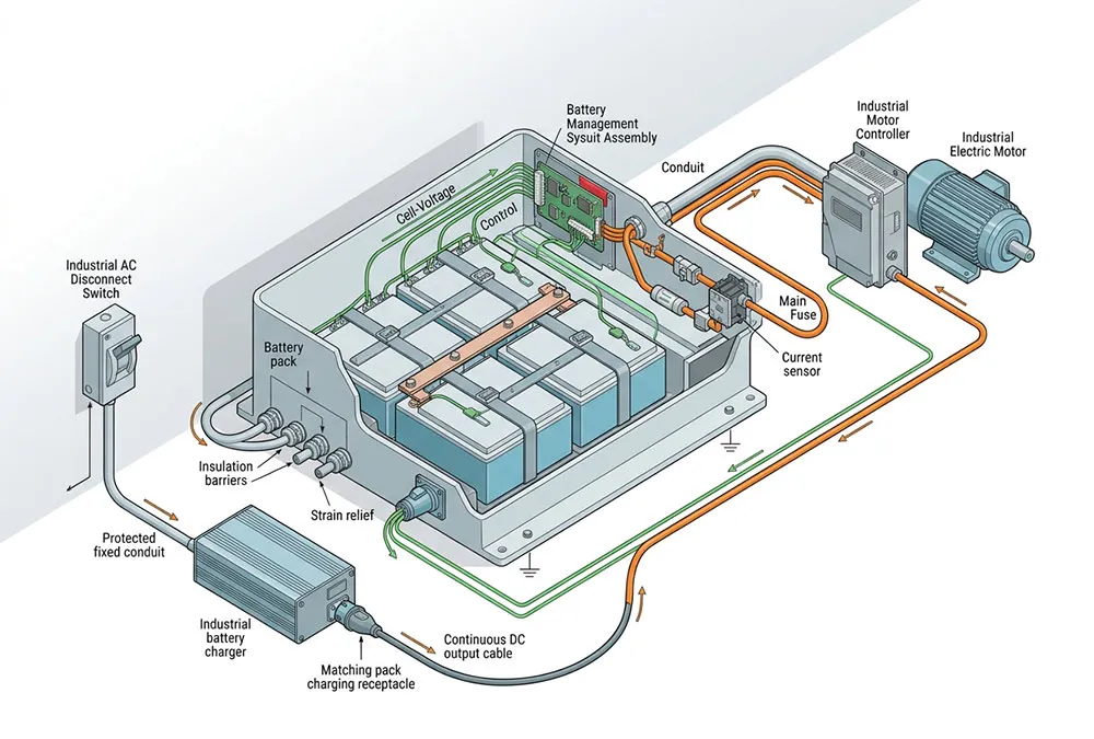
A complete pack also needs busbars, wiring, a fuse, switching devices, current and temperature sensors, a BMS, an enclosure and serviceable connectors. Some systems add heating, cooling, displays, telemetry or CAN/RS485 communication. These parts add mass and volume, so cell-level values should not be presented as complete-pack performance. Our guide to cell, module and pack energy density explains why the measurement boundary matters.
The enclosure and interfaces make the pack application-specific. A traction pack may need to tolerate vibration, peak motor current and regenerative current. A stationary pack may prioritize inverter communication, installation clearances and thermal propagation controls. Nominal voltage alone cannot prove that a battery is compatible.
What Does the Battery Management System Actually Control?
A useful way to understand a BMS is as four linked functions:
- Monitor: measure individual cell voltages, pack current, temperatures and internal status.
- Decide: compare those measurements with configured limits, delays and operating states.
- Act: permit, reduce or stop charging/discharging through switching devices or communication commands.
- Record and communicate: estimate SOC, report allowable power, store faults and exchange data with a charger or controller.
A BMS cannot repair a weak cell, cool an inadequate enclosure, reduce resistance in an undersized cable or prove that a battery has passed a required safety standard. For a closer industrial example, see how a 48 V LiFePO4 BMS monitors and protects a pack.
Why can SOC disagree with voltage?
State of charge (SOC) is an estimate of remaining usable charge; it is not measured like liquid in a transparent tank. A BMS may combine current integration, cell voltage, temperature and a battery model. Analog Devices explains in its SOC and SOH estimation guide that accurate estimation depends on voltage, current, individual cell data, temperature and application conditions.
The issue is especially visible with LFP. Its voltage remains relatively flat across much of the usable range, so a small voltage difference can correspond to a meaningful SOC difference. An Analog Devices LFP fuel-gauging note explains why voltage-only estimation is difficult on this flat plateau.
If the display shows substantial charge but the equipment stops, collect rested and loaded pack voltage, minimum-cell voltage, current, temperature, SOC calibration state and the event log. This identifies whether the problem is estimation drift, voltage sag, a weak cell or an actual loss of usable capacity.
Why Temperature and Current Change Battery Behaviour
The same battery will not behave identically at every current and temperature. Higher current produces more voltage drop across resistance and more resistive heating. Low temperature slows transport and can cause the BMS to reduce or reject charging. High temperature accelerates unwanted reactions and can shorten service life even when it is not high enough to cause an immediate safety event.
OSHA’s Lithium-ion Battery Safety guidance identifies improper charging, physical damage and excessive heat or cold as factors that can contribute to failure. It also describes thermal runaway as a chain reaction in which heat from a failing cell can damage nearby cells. This is why “LFP chemistry” or “built-in BMS” should never be used as a complete safety argument.
If charging slows or stops in cold conditions, inspect cell temperature and the active charge limit before blaming the charger. If a connector becomes unusually warm, compare temperature and voltage drop across that connection under a known current. Do not defeat temperature limits, interlocks, fuses or BMS protection to keep the equipment running.
How Are Lithium-Ion Batteries Becoming Safer and Smarter?
Battery safety is not created by one “safe” chemistry or a single BMS switch. It comes from several layers that prevent a fault, detect it, interrupt it or limit its consequences. For a buyer, this matters because two packs built around the same nominal voltage and cathode chemistry can have very different protection, mechanical design and validation.
Safety improves through layers, not one component
- Cell design and manufacturing: consistent materials, electrode coating, separator integrity, contamination control and formation testing reduce the chance that a hidden defect enters the pack. Some cell formats also use purpose-designed pressure, temperature or current-interruption features, but those devices are not identical across every cell type.
- Electrical protection: correctly selected fuses, contactors or MOSFETs, insulation and conductors must interrupt or withstand the relevant fault current. A software limit cannot substitute for a properly coordinated physical current path.
- BMS monitoring: individual-cell voltage, pack current and temperature data allow the system to reduce or stop operation before defined limits are exceeded. Useful event records also make the cause of a trip easier to investigate instead of repeatedly resetting the pack.
- Mechanical and thermal design: cell restraint, spacing or barriers, thermal paths, controlled venting, ingress protection and impact protection are selected for the application. A mobile pack and a stationary cabinet may therefore require different solutions even when they use similar cells.
- System integration and validation: the charger, controller, enclosure, installation, operating procedure and maintenance plan must work with the battery. Model-specific testing and documentation are more meaningful than a general statement that the chemistry is safe.
UL Research Institutes’ explanation of lithium-ion battery safety mechanisms describes separator, selected cell-level devices and battery-management protection as different parts of the safety design. The examples are useful, but they should not be read as a claim that every industrial cell contains the same internal hardware.
What may change in the next generation of batteries?
The basic requirement will remain: ions need a stable path inside the cell, electrons need a controlled external path, and the system must keep voltage, current and temperature within suitable limits. Future development is increasingly focused on observing and managing those processes earlier and more accurately.
- More informative sensing: embedded or non-invasive sensors are being researched to observe pressure, strain, impedance, temperature distribution and chemical changes that ordinary terminal-voltage measurements may miss.
- Predictive battery management: richer operating data, physics-based models and digital twins may help distinguish gradual degradation from an immediate fault and schedule maintenance before lost service.
- Improved materials and interfaces: researchers are working on electrodes, electrolytes, coatings and internal interfaces that can support higher energy, faster charging, longer life or greater tolerance to abuse. Each improvement still creates trade-offs that must be tested at cell and pack level.
- Design for manufacturing and circularity: better production data, traceability, consistent quality control and end-of-life planning can connect the battery’s design, operating history and eventual recovery or recycling.
Europe’s BATTERY 2030+ research roadmap identifies sensing, self-healing, battery management, digital twins, new chemistries, manufacturing and recycling as long-term research areas. These are development directions, not evidence that every feature is commercially mature or available in a particular product.
Solid-state technology is one example of why that distinction matters. Replacing conventional liquid electrolyte with a solid electrolyte may change ion transport, packaging and some failure mechanisms. However, the U.S. Department of Energy’s Energy Storage Safety Strategic Plan notes that emerging systems still need rigorous analysis of their own failure modes. “Solid-state” should therefore be treated as a technology description, not an automatic safety certificate.
What this means for a buyer today
Ask suppliers to separate features already implemented and verified in the offered model from development-roadmap claims. Request the supported sensor inputs, BMS functions, fault records, charger interface, thermal design and model-specific test evidence that can be reviewed now.
What Common Battery Symptoms Can Tell You
A symptom is not a diagnosis. The table below shows the minimum evidence that helps separate normal behaviour from an integration or service issue.
| Observed symptom | Operational consequence | Evidence to collect | Possible mechanisms | Practical next step | Do not assume |
|---|---|---|---|---|---|
| Voltage falls under a heavy load and recovers at rest | Reduced lift or traction performance, nuisance shutdown or an incorrect battery-replacement decision | Current, rested/loaded voltage, cell spread, cable and connector drop | Normal resistance, loose connection, undersized conductor or higher cell resistance | Compare measured drop with the approved design at the same current | That capacity has disappeared |
| Pack shuts down while average voltage looks usable | Equipment stops before the displayed pack energy appears depleted | Minimum-cell voltage, current, temperature and BMS event | One cell reaches its lower limit first; peak current exceeds the configured limit | Review cell-level data and the load profile before resizing the pack | That the BMS itself is defective |
| SOC drops suddenly near the end | Unreliable runtime planning, missed work completion or unnecessary charging | Coulomb count, calibration state, actual capacity, cell spread and load | Estimation drift, ageing, imbalance or load-dependent cutoff | Follow the approved calibration and capacity-test procedure | That pack voltage alone gives accurate SOC |
| Charger cycles on and off near full | A missed charging window, repeated service calls or uncertainty about whether the pack is ready | Maximum cell voltage, cell spread, charge current, temperature and limit flags | High-cell cutoff, balancing delay, charger mismatch or normal termination logic | Compare the event with the approved charger/BMS charging strategy | That a higher charge voltage is the solution |
| Charge is reduced or rejected in cold or hot conditions | Delayed charging, reduced available power or equipment waiting for temperature recovery | Cell and ambient temperature, requested/actual current, BMS limit reason | Temperature-based derating or protection | Correct the thermal condition or use an approved thermal strategy | That protection should be bypassed |
Need help interpreting a battery symptom?
Send the pack voltage, minimum-cell voltage, current, temperature, charger information, duty cycle and BMS fault record. The review will identify which measurements are still missing and which compatibility questions should be resolved first.
How the Same Working Principle Changes Across Applications
All lithium-ion batteries rely on coupled ion and electron movement, but a suitable pack is defined by its application. The most important mechanism or design constraint changes with the equipment.
| Application | What matters most | Buyer question |
|---|---|---|
| Forklifts and material handling | Peak traction/lift current, voltage sag, opportunity charging, mass, fit and charger coordination | Can the pack support the actual peaks and charging windows without nuisance shutdowns? |
| AGVs and AMRs | Frequent shallow cycling, automated charging alignment and communications | Can the battery, charger and vehicle exchange limits reliably? |
| Home and commercial storage | Inverter voltage window, long dwell periods, monitoring and installation safety | Are the inverter interface and installation protections matched to the pack? |
| LSEVs and utility vehicles | Acceleration and regenerative current, vibration, weather exposure and mounting | Has the pack been integrated with the controller and vehicle structure? |
| Cleaning and access equipment | Compact compartments, intermittent peaks, connector access and indoor charging workflow | Do the dimensions, current capability and service access fit the machine? |
AnengJi provides LiFePO4 battery options for industrial, mobility and storage applications. A standard-format pack can be a useful starting point, while an application-specific pack may change enclosure, mounting, connector, BMS settings or communications. Neither should be treated as a universal drop-in replacement until voltage window, current, dimensions, mass, restraint, charger interface and equipment approval have been reviewed.
LFP is one member of the lithium-ion family, not a synonym for every lithium-ion battery. Chemistry selection should follow the application’s energy, power, temperature, service-life, safety and cost priorities. A separate comparison of where LiFePO4 fits—and where it may not can support that decision.
What Should an Industrial Buyer Verify Before Choosing a Pack?
A useful quotation needs more than nominal voltage and amp-hours. Provide the following data so the battery can be evaluated as part of the machine rather than as a stand-alone box:
- Electrical: controller operating-voltage window, continuous current, peak current and duration, regenerative current, runtime or usable-energy target.
- Charging: charger model, voltage/current profile, connector, charging windows and communication requirements.
- Mechanical: compartment dimensions, connector/service clearance, mounting, restraint, target mass and handling method.
- Environment: minimum and maximum cell/ambient temperatures, vibration, dust/water exposure and indoor/outdoor use.
- Controls: CAN/RS485 protocol, interlocks, displays, telemetry, diagnostic access and fault response.
- Commercial and compliance: destination, application, quantity, transport route and the model-specific documents required by the buyer or authority.
For European industrial applications, the official scope of IEC 62619:2022 includes secondary lithium cells and batteries used in industrial stationary and motive applications, with examples such as energy storage, forklifts and AGVs. The existence of that standard does not prove a particular product complies. Ask for a report or certificate showing the exact model, edition, issuing body, dates and covered configuration. Requirements may also differ by application and destination, including the United States, Central Asia and African markets.
Turn your equipment data into a battery requirement
An application review can organize your voltage window, peak current, duty cycle, charger, compartment, temperature, connector and communication requirements into a practical specification checklist before a pack is selected.
Frequently Asked Questions About How Lithium-Ion Batteries Work
What happens when a lithium battery “dies”?
“Dead” can mean three different things. The pack may simply be discharged; the BMS may have opened the current path because one limit was reached; or the aged battery may no longer deliver the required capacity or power. Read the BMS event, individual cell voltages and loaded behaviour before deciding which condition applies.
What is the main disadvantage of lithium-ion batteries?
There is no single disadvantage that applies equally to every chemistry and application. Buyers must account for charge control, BMS and thermal design, ageing conditions, integration work, procurement cost and application-specific safety evidence. The correct trade-off depends on the duty cycle and the consequences of downtime or added mass.
How risky are lithium-ion batteries?
They store substantial energy and can present electrical, chemical and thermal hazards if cells are defective, damaged, improperly charged or poorly integrated. Risk is managed through cell quality, pack design, protection, thermal paths, validation, installation, compatible charging, inspection and trained operation—not by chemistry name alone.
Can a lithium-ion battery charge while the equipment is operating?
It depends on the system’s power-path architecture. The charger may power the load and provide any remaining current to the battery, or the load may temporarily exceed charger output and draw net current from the pack. Confirm the charger, BMS and controller design rather than assuming the battery is simultaneously charging and discharging in equal measure.
Is a BMS the same as a battery charger?
No. The charger controls the electrical power used to charge the pack. The BMS monitors battery conditions, communicates limits and interrupts the current path when necessary. A suitable system needs both functions coordinated correctly.
Why is the separator necessary if the electrolyte carries ions?
The electrolyte provides an ion-conduction path. The separator keeps the electrodes physically apart while remaining porous to lithium ions. Without that separation, electrons could cross internally through a short circuit instead of flowing through the useful external load.
Related Articles

Related Posts
 https://anengjibattery.com/wp-content/uploads/2026/10/AnengJIBattery-Lithium-Ion-Power-in-Industrial-Operation.webp
675
1000
Battery Expert Team
https://anengjibattery.com/wp-content/uploads/2025/06/logo2-300x138.png
Battery Expert Team2026-10-29 03:43:242026-10-29 03:46:52How Does a Lithium-Ion Battery Work and Stay Protected?
 https://anengjibattery.com/wp-content/uploads/2026/10/AnengjiBattery-Is-a-Lithium-Ion-Battery-for-3PL-the-Right-Fleet-Choice.webp
675
1000
Battery Expert Team
https://anengjibattery.com/wp-content/uploads/2025/06/logo2-300x138.png
Battery Expert Team2026-10-28 07:16:182026-10-28 07:17:07Is a Lithium-Ion Battery for 3PL the Right Fleet Choice?
 https://anengjibattery.com/wp-content/uploads/2026/10/AnengjiBattery-Forklift-Battery-Weight-in-a-Working-Warehouse.webp
675
1000
Battery Expert Team
https://anengjibattery.com/wp-content/uploads/2025/06/logo2-300x138.png
Battery Expert Team2026-10-27 02:59:132026-10-27 02:59:15How Does Forklift Battery Weight Affect Stability and Fit?
 https://anengjibattery.com/wp-content/uploads/2026/10/AnengJIBattery-Top-10-Forklift-Battery-Manufacturers-for-Cold-Storage.webp
675
1000
Battery Expert Team
https://anengjibattery.com/wp-content/uploads/2025/06/logo2-300x138.png
Battery Expert Team2026-10-26 09:12:412026-10-27 02:59:38Top 10 Forklift Battery Manufacturers for Cold Storage



Leave a Reply
Want to join the discussion?Feel free to contribute!