
What Does a BMS Do in an Electric Tricycle Battery?
September 7, 2026 / Battery Expert Team / Battery Basics
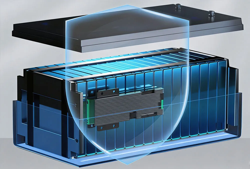
A Battery Management System (BMS) monitors and protects the cells inside a lithium battery while managing charging and discharging within configured limits. In an electric tricycle, the BMS must be matched with the battery cells, motor controller, charger and actual operating conditions. Integrating a properly configured electric tricycle battery BMS into your pack setup is what keeps commercial three-wheelers running reliably without sudden power dropouts on heavy delivery climbs. Honestly, seeing fleet managers swap out expensive lithium packs because an cheap off-the-shelf control board kept tripping under heavy loads happens far too often in this industry.
Market demand for reliable light electric commercial vehicles continues to surge globally. According to the Global E-Transportation Logistics Market Report 2025 by BloombergNEF, light commercial electric three-wheelers will account for over 38% of last-mile express deliveries in urban centers across Asia and Latin America by 2028. However, scaling a fleet requires more than high capacity cells. Without a well-engineered electric tricycle battery BMS, operating under high ambient heat, rough urban roads, and heavy cargo payloads will rapidly lead to cell imbalance, excessive thermal wear, or sudden acceleration cutoffs. This complete technical guide explores how a BMS works, how to properly match continuous and peak current thresholds, diagnostic steps for power loss, and what critical specifications buyers must review before issuing a volume procurement order.
Quick Answer
A BMS protects an electric tricycle battery by monitoring cell voltage, current and temperature, balancing cells and triggering protection when operating conditions exceed configured limits.
Core Concept: A BMS does not determine battery capacity. Ah describes battery capacity, while the BMS determines how the battery can be safely charged and discharged within its configured limits.
What Is a BMS in an Electric Tricycle Battery?
To put it simply, a battery management system is the electronic intelligence residing inside a lithium battery pack. Lithium cells, whether Lithium Iron Phosphate (LiFePO4) or Nickel Manganese Cobalt (NMC), are sensitive to operational extremes. Unlike older lead-acid batteries that tolerate mild overcharging, lithium chemistries require precise control over every individual cell in the series string.
What Does BMS Stand For?
BMS stands for Battery Management System. It is an integrated electronic circuit board that monitors internal electrical states, calculates state metrics, protects hardware from extreme conditions, and communicates cell status to external components like motor controllers or smart instrument panels.
How a Battery Management System Works
The BMS sits directly between the raw lithium cell matrix and the external terminal leads connected to your vehicle’s wiring harness. It constantly samples voltage taps connected to every parallel cell group, monitors total current passing through shunt resistors or Hall sensors, and measures internal temperature via NTC thermistors. When electrical parameters remain within safe factory parameters, solid-state switches (MOSFETs) or heavy-duty contactors stay closed, allowing current to flow freely. The moment a parameter crosses a safe threshold, the BMS opens its switches to isolate the cells from the vehicle load or charger.
BMS vs Battery Protection Board
buyers frequently confuse basic hardware protection boards with full-featured battery management systems. Here is how these electronic architectures compare across functional tiers:
| Control Board Type | Main Functionality | Vehicle Suitability | Buyer Advantage / Operational Benefit |
|---|---|---|---|
| Basic Protection Board | Basic overcharge, over-discharge, and hardware overcurrent cutout. No data logging or active balancing. | Low-power electric bicycles, small personal scooters. | Ultra-low cost; simple plug-and-play wiring. |
| Standard BMS | Monitoring + multi-stage protection + passive cell balancing + precise thermal cutoffs. | Standard passenger electric rickshaws, light delivery trikes. | Prevents cell imbalance over time, extending pack lifespan to 3,000+ cycles. |
| Smart BMS | Includes standard features plus real-time Bluetooth/App monitoring, event logging, and dynamic parameter tuning. | Commercial fleet vehicles, regional rental tricycles. | Enables on-site field diagnostics without opening the sealed battery enclosure. |
| Communication BMS | Full CANbus or RS485 protocol integration with vehicle controller, smart charger, and telemetry hardware. | Heavy cargo tricycles, automated logistics fleets. | Real-time cloud tracking of battery health (SOH), preventing unexpected route breakdowns. |
What Does a BMS Do in an Electric Tricycle Battery?
An electric tricycle battery BMS performs multiple critical functions simultaneously to maintain system stability, vehicle safety, and operational efficiency. Deploying a commercial electric tricycle lithium battery BMS ensures your power pack operates reliably under harsh working environments.
| BMS Function | What It Does | Why It Matters in Commercial Trikes | Buyer Advantage / Operational Benefit |
|---|---|---|---|
| Cell Voltage Monitoring | Monitors individual cell group voltages in real time. | Helps prevent abnormal cell overvoltage or undervoltage. | Prevents single weak cell failure from ruining the entire battery pack. |
| Current Monitoring | Measures continuous and peak charge/discharge current. | Helps control excessive current draw during heavy acceleration. | Protects internal wiring and busbars from thermal destruction under heavy cargo. |
| Temperature Monitoring | Monitors cell matrix and power MOSFET temperatures. | Protects against abnormal thermal runaway or cold-charging damage. | Extends pack safety during high-ambient-temperature summer shifts. |
| Cell Balancing | Bleeds off excess charge from high cells (passive) or redistributes energy (active). | Reduces cell voltage differences over repeated charge cycles. | Restores maximum usable range by keeping all cell groups synchronized. |
| Protection Control | Disconnects solid-state switches upon detecting a fault condition. | Prevents continued operation under hazardous fault conditions. | Eliminates catastrophic short-circuit risks on rugged roads. |
| SOC Monitoring | Calculates state-of-charge based on voltage and coulomb counting. | Shows accurate remaining battery energy on the dashboard. | Eliminates driver range anxiety with precise kilometer-to-empty data. |
| Communication | Transmits operational telemetry over CANbus, RS485, or UART lines. | Enables smart vehicle integration and cloud fleet management. | Allows remote diagnostic monitoring across large commercial fleets. |
Cell Voltage Protection
Each lithium cell chemistry operates within tight voltage boundaries. A typical LiFePO4 cell has a nominal voltage of 3.2V, with a maximum charge limit of 3.65V and a low-discharge floor of 2.5V. If a cell drops below its cut-off limit, internal copper dissolution can occur, causing permanent internal short circuits. Conversely, exceeding the upper voltage ceiling causes electrolyte breakdown and thermal gas generation. The BMS constantly tracks individual cell taps, triggering overvoltage protection (OVP) or undervoltage protection (UVP) instantly if any single cell strays past safety boundaries.
Overcurrent and Short-Circuit Protection
Commercial electric tricycles draw significant current when launching from a stop or climbing steep gradients under heavy cargo loads. The BMS incorporates short-circuit protection (SCP) and multi-stage overcurrent protection (OCP). If current draw exceeds programmed continuous or burst thresholds, the BMS opens its switches within microseconds to shield internal cell interconnects, busbars, and downstream controllers from severe thermal damage.
Temperature Protection
Temperature extremes severely impact lithium battery health. According to the 2026 IEEE Automotive Battery Thermal Management Standards , charging a standard lithium cell at temperatures below 0°C leads to immediate metallic lithium plating on the anode, creating microscopic dendrites that can pierce cell separators. The BMS utilizes multiple NTC temperature sensors embedded throughout the pack matrix. It triggers high-temperature discharge cut-offs (typically at 60°C to 65°C) and prevents low-temperature charging to ensure battery integrity.
Cell Balancing
Due to minor manufacturing tolerances, individual cells inside a series string exhibit slight variances in capacity and internal resistance. Over dozens of charge cycles, these small variations widen. During charging, the highest-voltage cell group hits its top cut-off limit first, forcing the charger to stop even if other cells are only 80% charged. During discharge, the weakest cell hits the low voltage floor first, stopping the entire vehicle prematurely. A quality electric tricycle battery BMS employs passive or active cell balancing to equalize voltages across all series groups, ensuring maximum usable range over the entire life of the pack.
SOC and Battery Data Monitoring
Basic voltage readings yield inaccurate State of Charge (SOC) estimations for LiFePO4 chemistry due to its extremely flat discharge curve. An advanced electric tricycle battery BMS uses Coulomb counting—integrating real-time current measurements over time—to calculate precise remaining charge percentage. This data is transmitted to vehicle dashboards, preventing drivers from running out of power midway through delivery routes.
CAN, RS485 and Smart BMS Communication
In modern fleet applications, the battery is not an isolated component; it is an integrated sub-system. Using CANbus or RS485 communication protocols, a smart BMS streams real-time telemetry (including individual cell voltages, temperature, State of Health [SOH], fault codes, and current draw) directly to the vehicle motor controller and fleet telematics gateway. This communication allows motor controllers to smoothly roll back power output under thermal or low-voltage conditions rather than shutting down the vehicle abruptly.
Unsure About Your Fleet’s BMS Communication Needs?
We configure custom CANbus and RS485 smart BMS setups tailored to your motor controller and vehicle displays. Send us your system specifications for an engineering evaluation!
How Does an Electric Tricycle Battery BMS Protect the Vehicle?
Understanding the hardware architecture behind vehicle protection clarifies why the BMS is essential for operational reliability. A properly configured system forms a complete protection chain across the vehicle’s high-voltage system.
Electric Tricycle Battery Protection Architecture
Battery Cells → Voltage / Current / Temperature Sensing → BMS Electronics → MOSFETs / Contactor → Battery Output Terminals → Motor Controller → Electric Traction Motor
Note that the BMS does not directly command or override the motor controller logic. Instead, it protects the powertrain by controlling high-power solid-state switches (MOSFETs) or electromechanical contactors placed in series with the battery output terminals. When a critical threshold is breached, the BMS interrupts the primary circuit to stop current flow.
What Happens When a Protection Limit Is Triggered?
When an operational limit is exceeded—such as total current draw surpassing safe limits during a heavy hill climb—the BMS executes a protective disconnect. Depending on the programmed severity and recovery logic, the system responds in one of two ways:
- Automatic Recovery: Once the fault condition clears (e.g., cell temperature drops below threshold, or throttle is released to lower current demand), the BMS clears the fault state and re-engages output after a set delay.
- Latch-off / Manual Reset: For severe fault events like short circuits or severe individual cell overvoltage, the BMS latches the switch open. Power restoration requires connecting an active charger or executing a manual system power reset.
Why the BMS May Disconnect Battery Output
Unexpected power loss during operation can be frustrating for drivers, but the BMS triggers output cut-offs for valid protective reasons:
- Single cell voltage dropped below the safe low threshold (UVP).
- Continuous acceleration demand exceeded overcurrent limits (OCP).
- Internal power MOSFETs or battery cells reached thermal limits (OTP).
- Physical wire harness damage caused an external short-circuit (SCP).
- Severe cell imbalance created dangerous voltage spreads between series strings.
How Many Amps Should an Electric Tricycle Battery BMS Handle?
Selecting the correct current rating for a 60V electric tricycle battery BMS or a 72V electric tricycle battery BMS is one of the most vital commercial procurement choices. A mismatched current specification will compromise vehicle performance or increase unnecessary component costs.
Continuous vs Peak BMS Current
When reviewing BMS current specifications, buyers must distinguish between continuous current and peak burst current ratings:
- Continuous Current Rating: The maximum amperage the BMS power board can pass indefinitely under ambient operating conditions without exceeding safe thermal thresholds.
- Peak Current Rating: The maximum short-duration amperage (typically rated for 3 to 30 seconds) the BMS can sustain without tripping overcurrent protection. This handles temporary surge demands during initial vehicle launch, rapid acceleration, or steep incline climbing.
How Motor Power Affects Battery Current
To estimate the required continuous current, calculate the electrical power draw using the standard system voltage relationship:
Battery Current (A) ≈ Electrical Power (W) / Battery Voltage (V)
Consider a 5,000W (5kW) nominal motor operating across two common system voltage configurations:
- At 48V Nominal System: 5,000 W / 48 V = 104.1 A continuous current draw.
- At 72V Nominal System: 5,000 W / 72 V = 69.4 A continuous current draw.
This is a simplified estimate. Actual battery current depends on controller limits, motor efficiency, operating conditions and system losses.
Motor Rated Power vs Controller Current vs BMS Current
A frequent error among procurement teams is assuming that motor rated power directly equals the required BMS current rating. In real vehicle design, these specifications represent distinct limits across the drive system:
| System Component | Engineering Definition | Role in Current Sizing | Buyer Advantage / Operational Benefit |
|---|---|---|---|
| Motor Rated Power | Continuous mechanical power output rating specified by the motor manufacturer (e.g., 1,500 W, 3,000 W). | Establishes baseline nominal power demands. | Helps determine overall vehicle class and baseline speed capability. |
| Controller Current Limit | Maximum electrical current the motor controller is configured to draw from the battery. | Dictates the actual maximum electrical current demand. | Prevents motor overheating and controls maximum acceleration torque. |
| BMS Continuous Current | The continuous amperage capacity the BMS circuit and MOSFETs can safely pass. | Must equal or exceed maximum vehicle continuous operating draw. | Ensures the battery can run at full vehicle speed without thermal shut-offs. |
| BMS Protection Limit | The exact overcurrent threshold where BMS protective disconnect triggers. | Set safely above motor controller peak burst settings. | Prevents nuisance cut-offs while climbing steep hills under heavy load. |
Crucial Engineering Rule: Motor rated power ≠ controller current limit ≠ BMS continuous current ≠ BMS protection threshold. The BMS continuous current rating must be matched to the motor controller’s real-world current limit, not merely the motor’s nominal power label.
Can a Low-Rated BMS Cause an Electric Tricycle to Lose Power?
Yes. An undersized BMS current specification is a leading root cause of sudden power loss in commercial three-wheelers under load. On technical community forums like Reddit (e.g., r/ebikes and r/EVconversion), fleet mechanics frequently document issues where an electric tricycle accelerates normally on flat roads but cuts out completely the moment it encounters a hill or carries heavy cargo. This phenomenon is directly tied to BMS current cut-offs.
What Happens When the BMS Current Rating Is Too Low?
When a driver accelerates hard under full payload, the motor controller requests peak burst current. If the controller’s current demand exceeds the programmed threshold of an undersized BMS, the system triggers protection:
High Load / Heavy Cargo → Controller Increases Current Demand → BMS Overcurrent Protection Threshold Reached → BMS Opens MOSFET Switches → Battery Output Disconnects → Vehicle Instantly Loses Power
Note: A cutoff is not automatically proof that the BMS is defective. In many cases, the BMS is simply executing its engineered protection job because it was paired with an oversized controller or undersized cell matrix.
Why Does the Battery Voltage Drop Under Load?
Sudden cut-offs are often triggered by severe voltage drop (sag) under high current draw. When current passes through internal cell resistance, busbars, and harness connections, voltage drops according to Ohm’s Law ( V_sag = I * R_internal). Factors contributing to voltage drop include:
| Voltage Drop Variable | Impact on Battery Performance | Buyer Advantage / Practical Solution |
|---|---|---|
| High Cell Internal Resistance | Aged or low-grade cells experience severe voltage sag under acceleration. | Specify tier-1 A-grade LiFePO4 cells with internal resistance < 0.5 mΩ (or < 0.5 milliohms). |
| Weak or Aged Cells | Weak cell groups hit low-voltage cut-off (UVP) prematurely under load. | Utilize smart BMS with cell balancing to maintain string uniformity. |
| Cold Temperature | Cold ambient temperatures increase electrolyte viscosity and internal impedance. | Select battery packs with integrated BMS thermal heating pads for cold climates. |
| Undersized Harness Wiring | Thin battery cables create high electrical resistance and localized heating. | Ensure battery interconnects use appropriate copper busbar cross-sections. |
Is the BMS Actually Causing the Cutoff?
When diagnosing power cut-offs, field technicians should execute a systematic diagnostic process to isolate the root cause before replacing components:
BMS Cutoff Diagnostic Path:
1. Power loss occurs during vehicle launch or acceleration →
2. Measure total pack voltage under load using a logging multimeter →
3. Read individual cell voltages via BMS Bluetooth App or communication interface →
4. Check BMS fault event logs for Overcurrent (OCP) or Undervoltage (UVP) flags
5. Compare controller peak current setting against BMS overcurrent threshold →
6. Inspect main power connectors and cable lugs for signs of high-resistance thermal discoloration →
7. Identify exact root cause (Undersized BMS vs Aged Cells vs Loose Wiring).
How Do Battery, BMS and Motor Controller Work Together?
Building a durable electric vehicle powertrain requires seamless electrical balance across all major components. The battery cells, BMS, motor controller, and traction motor form an integrated chain.
Battery Capacity vs Battery Discharge Capability
One of the most widespread misunderstandings in battery specification is confusing Amp-hours (Ah) with Amperes (A):
- Capacity (Ah): Tells you how much energy the battery stores (determines total vehicle range).
- Discharge Capability (A): Tells you how much current the battery can safely deliver at any given instant (determines top speed and torque power).
Critical Distinction: A 40Ah battery pack does not mean it can only deliver 40 Amps of current! A high-drain 40Ah LiFePO4 pack built with 3C-rated cells can continuously deliver 120 Amps (40 Ah * 3C = 120 A), provided the installed BMS is rated for 120A continuous service.
How Controller Current Affects BMS Selection
The motor controller regulates power delivery to the motor windings.If your controller is configured for a 100A maximum input current, installing an electric tricycle battery BMS current rating of only 60A creates an operational mismatch. Under full acceleration, the controller will demand 100A, triggering the BMS’s overcurrent protection instantly.. Always size the BMS continuous current rating to meet or exceed the controller’s continuous input specification, with peak BMS current set above the controller’s peak burst limit.
Why the Battery Should Not Be the System Bottleneck
When designing commercial vehicle fleets, the battery pack and BMS should offer higher current capability than the motor controller demands. When the battery system is undersized, current overload causes voltage sag, high thermal stress on power MOSFETs, accelerated cell degradation, and frequent nuisance shut-offs on delivery routes.
How Does BMS Voltage Match a 48V, 60V or 72V Tricycle Battery?
Never select an electric tricycle battery BMS based solely on generic nominal labels like “48V” or “60V”. Correct BMS selection requires matching the exact cell chemistry and series cell count (S).
Nominal Voltage vs Actual Battery Voltage
A battery label indicates nominal voltage, but actual system voltage varies during charge and discharge cycles. A “48V” system operates over a wide voltage range depending on cell chemistry:
| Battery Platform | Cell Chemistry | Series Configuration | Nominal Pack Voltage | Full Charge Voltage | Low Cut-off Voltage |
|---|---|---|---|---|---|
| 48V System | LiFePO4 (LFP) | 16S | 51.2V | 58.4V | 40.0V |
| 48V System | NMC / Ternary | 13S | 48.1V | 54.6V | 39.0V |
| 60V System | LiFePO4 (LFP) | 20S | 64.0V | 73.0V | 50.0V |
| 60V System | NMC / Ternary | 16S | 59.2V | 67.2V | 48.0V |
| 72V System | LiFePO4 (LFP) | 24S | 76.8V | 87.6V | 60.0V |
| 72V System | NMC / Ternary | 20S | 74.0V | 84.0V | 60.0V |
Cell Chemistry and Series Configuration
As illustrated in the table above, .a standard 48V electric tricycle battery BMS designed for a 16S LiFePO4 battery pack (51.2V nominal, 58.4V max charge) uses completely different overvoltage and undervoltage parameters than a 13S NMC pack (48.1V nominal, 54.6V max charge). Connecting a 13S NMC BMS to a 16S LiFePO4 pack will destroy the circuit board due to incorrect voltage taps and misaligned series monitoring channels.
How Does a BMS Affect Electric Tricycle Charging Safety?
Charging is one of the most electrically demanding phases of battery operation. A properly matched BMS works alongside the charger to maintain charging safety.
Overcharge Protection
If a charger fails to taper current or experiences an internal voltage regulation fault, the BMS serves as a secondary line of defense. The moment any individual cell group hits its overvoltage threshold (e.g., 3.65V for LiFePO4), the BMS opens its charge MOSFETs, cutting off incoming current immediately to prevent thermal runaway.
Charging Current Protection
Lithium cells have maximum safe fast-charging current limits (typically 0.5C to 1C). Pushing excessive charging current through cells causes localized overheating and lithium plating. The BMS enforces a Charge Overcurrent Protection (COCP) limit, opening the charging circuit if an incorrect or high-amperage charger is connected.
Temperature Protection During Charging
As highlighted in the 2025 Global Lithium Battery Safety Guidelines , charging lithium packs below 0°C or above 45°C accelerates cell degradation. A quality BMS prevents charging input whenever internal probe temperatures drop below 0°C or exceed safe thresholds, ensuring long-term battery health.
BMS and Charger Compatibility
Crucial Rule: A BMS does not replace a properly matched charger. The charger must supply the correct constant current / constant voltage (CC/CV) profile and match the nominal pack voltage. The BMS serves as a safety backup and cell balancing manager, not a primary voltage step-down regulator.
What BMS Specifications Should You Check Before Buying?
When sourcing commercial lithium batteries or evaluating an electric tricycle battery BMS replacement project, review this technical parameter matrix before issuing purchase orders:
| BMS Technical Parameter | What Procurement Buyers Should Verify | Buyer Advantage / Operational Benefit |
|---|---|---|
| Series Count ($S$) & Voltage | Match exact series cell count (16S, 20S, 24S) and cell chemistry limits. | Prevents immediate voltage fault triggers and hardware destruction. |
| Continuous Discharge Current | Must equal or exceed maximum continuous current draw of the motor controller. | Guarantees full vehicle speed without continuous thermal throttling. |
| Peak Discharge Current & Time | Verify peak amperage rating and delay time (3 to 30 seconds) for launch acceleration. | Eliminates nuisance power loss while launching with heavy freight. |
| Charge Current Limit | Must accommodate high-output fast chargers without tripping protections. | Enables fast opportunity charging during shift breaks. |
| Cell Balancing Current | Cell Balancing Current: Check balancing method (Passive 30-100 mA vs Active 1-2 A). | Keeps large-capacity cells (100Ah) balanced over long shifts. |
| Communication Protocols | Verify isolated CANbus, RS485, UART, or Bluetooth hardware compatibility. | Enables fleet cloud monitoring and predictive maintenance tracking. |
| Thermal Sensor Channels | Ensure multiple NTC sensors monitor cell matrix and power MOSFETs. | Prevents localized hot-spots from damaging internal cell packs. |
| Protection Recovery Logic | Check whether fault recovery is automatic, time-delayed, or charger-triggered. | Reduces driver downtime by recovering automatically from minor transients. |
Is a Higher-Amp BMS Always Better?
No. Selecting a higher current rating does not automatically make an electric tricycle battery better, safer, or more powerful. In fact, over-specifying a BMS without considering total battery construction creates hidden safety risks.
Battery Power Capability Chain
Cell C-Rate Discharge Limit → Parallel Cell Group Count → BMS MOSFET Rating → Internal Copper Busbars → Terminal Wiring Gauge → Output Connectors → Thermal Dissipation Housing
Installing a 150A BMS onto a low-cost battery pack whose cells, internal busbars, or terminal wiring can only safely support 50A does not turn it into a 150A battery. If an external short circuit or overload occurs, an over-sized BMS may fail to trip overcurrent protection in time, allowing thin internal busbars or low-C cells to overheat, melt, or catch fire. The BMS current rating must always be sized to match the lowest-rated link in the battery’s internal electrical chain.
How Does BMS Selection Differ for Passenger and Cargo Electric Tricycles?
Commercial application profiles alter the mechanical, thermal, and electrical demands placed on a lithium battery management system.
| Vehicle Application | Main Operational Demands | Recommended BMS Architecture | Buyer Advantage / Operational Benefit |
|---|---|---|---|
| Passenger Tricycles / Auto Rickshaws | Frequent stop-and-go driving, moderate passenger payloads, 40-60 km daily routes. | 60V / 72V, 50A – 80A Continuous BMS with passive balancing and thermal protection. | Cost-effective reliability for passenger urban transport fleets. |
| Light Express Cargo Trikes | High daily mileage (80-120km), rapid parcel delivery, frequent acceleration bursts. | 60V / 72V, 80A – 100A Continuous Smart BMS with Bluetooth or RS485 telemetry. | Real-time battery diagnostic tracking for urban logistics operators. |
| Heavy Cargo & Industrial Trikes | Heavy freight payloads (400-800kg}), steep incline climbing, continuous high current draw. | 72V, 120A – 200A Continuous BMS with active balancing, CANbus, and heavy heat sinks. | Prevents thermal shutdown during high-torque, heavy-payload climbs. |
| Commercial Rental Fleets | Multi-driver usage, fast battery swapping, continuous multi-shift operations. | Custom Smart BMS with CANbus, Cloud Telematics, and SOC/SOH algorithm tracking. | Maximizes fleet uptime and provides remote health diagnostics. |
Passenger Electric Tricycle BMS Requirements
Passenger rickshaws prioritize smooth acceleration, passenger safety, and reasonable cost structures. Sizing an 80A continuous BMS with multi-point temperature sensors provides ample headroom for typical passenger loads while maintaining budget efficiency.
Cargo Electric Tricycle BMS Requirements
Cargo delivery vehicles operate under variable weight conditions. When fully loaded with parcels, current draw during launch increases significantly. Sizing a BMS with a high peak burst multiplier (2.5x to 3x continuous rating for 10 seconds) prevents nuisance tripping during urban stop-and-go delivery runs.
Heavy-Load and Commercial Fleet BMS Requirements
Industrial heavy-haul trikes require industrial-grade BMS hardware. Utilizing heavy aluminum heat sinks, active cell balancing (to manage cell heat generation during high discharge), and isolated CANbus communication allows fleet managers to integrate battery status into centralized telematics systems.
How to Check Whether an Electric Tricycle Battery BMS Is Working Properly
Maintaining fleet reliability requires periodic inspection of the battery management electronics. Field technicians can verify BMS health through structured testing procedures.
1. Check BMS Status and Fault Logs
On Smart BMS units equipped with Bluetooth or CANbus gateways, connect via mobile app or diagnostic software to review active fault codes, historical temperature spikes, overcurrent trip events, and cell balance history.
2. Check Total Pack Output Voltage
Measure total pack voltage at the main discharge terminals using a calibrated digital multimeter. Compare this reading against the sum of the individual cell group voltages. If output voltage reads 0V while internal cell group voltages are normal, the BMS has opened its protection MOSFETs due to a fault condition.
3. Check Individual Cell Group Voltages
Measure voltage across every series cell tap on the BMS balance harness. In a healthy pack, the voltage difference between the highest and lowest cell groups should be within 20 mV to 50 mV (0.02V – 0.05V). A cell voltage gap exceeding 200 mV indicates cell balance degradation or a failing BMS balancing channel.
4. Check Temperature Sensor Readings
Verify that all NTC temperature channels report realistic ambient values. A faulty thermistor reporting an erroneous 100°C reading will cause the BMS to permanently lock out battery discharge.
5. Review Protection Recovery Behavior
Verify that the BMS automatically clears temporary fault conditions (such as overcurrent or temporary thermal rise) once parameters return to normal operating ranges.
Safety Warning: Do not intentionally short-circuit, overload, or bypass a BMS to test its protection functions. Protection testing should only be performed using specialized lab equipment under controlled testing procedures.
When Do You Need a Custom BMS for an Electric Tricycle Battery?
While standard off-the-shelf control boards suit generic light vehicles, commercial fleets and OEM manufacturers frequently require a custom electric tricycle battery BMS to solve unique mechanical and electrical integration challenges.
Custom Continuous and Peak Current Thresholds
Off-the-shelf BMS units often feature rigid current limits. Custom BMS engineering allows exact tuning of continuous, peak, and short-circuit delay timers to match specific motor controller throttle maps perfectly.
Custom Voltage and Cell Protection Parameters
Custom parameter programming allows engineers to fine-tune overvoltage cut-offs, undervoltage recovery thresholds, and temperature limits based on specific cell manufacturer datasheets, extending total pack cycle life.
Custom Physical Form Factors and Spatial Geometry
Under-seat battery compartments or custom frame trays often present non-standard physical dimensions. Custom BMS circuit boards can be engineered in narrow, L-shaped, or dual-board stacked layouts to optimize internal space utilization.
CANbus / RS485 Protocol Customization
Fleet operators utilizing proprietary vehicle displays or cloud telematics gateways require customized CANbus baud rates, message IDs, and data frame structures to ensure seamless plug-and-play communication across vehicle systems.
OEM and ODM Commercial Battery Manufacturing
Partnering with an experienced manufacturer for custom OEM/ODM lithium battery manufacturing ensures that cells, BMS hardware, internal copper interconnects, and waterproof IP67 enclosures are built and tested as an integrated system.
What Should You Ask an Electric Tricycle Battery Supplier About the BMS?
Before issuing bulk purchase orders to an electric tricycle battery manufacturer, ask your supplier these crucial engineering questions:
- 1. What cell chemistry, brand, and grade are used in the pack? (Ensure tier-1 A-grade cells with matching internal resistance).
- 2. What is the true continuous and peak discharge current rating of the BMS? (Request continuous discharge temperature rise curves).
- 3. What are the exact BMS protection thresholds and recovery parameters? (Verify OVP, UVP, OCP, and OTP settings).
- 4. Can the BMS firmware parameters be customized for our motor controller? (Confirm parameter configurability via software).
- 5. Does the BMS support isolated CANbus or RS485 communication protocols? (Request CAN protocol mapping documentation).
- 6. How is the BMS and battery pack tested during production? (Verify EOL automated testing, burn-in procedures, and IP ratings).
- 7. Can you provide a prototype sample for field validation? (Test prototype units under real vehicle loads before mass ordering).
- 8. Can the same configuration be produced consistently at scale? (Ensure strict IQC/OQC quality management systems).
Electric Tricycle Battery BMS Buying Checklist
Use this procurement checklist when evaluating lithium battery management systems for electric three-wheeler projects:
1. Electrical System Compatibility
- Nominal System Voltage (48V, 60V, 72V) matched to motor controller
- Series Cell Count (16S, 20S, 24S) matched to cell chemistry
- Continuous Discharge Amperage exceeding maximum continuous motor draw
- Peak Burst Amperage handling steep incline launch acceleration
- Charge Amperage limit accommodating high-output fast chargers
2. Hardware Protection Functions
- Individual Cell Overvoltage (OVP) and Undervoltage (UVP) protection
- Multi-stage Overcurrent (OCP) and Short-Circuit (SCP) protection
- Multi-channel Temperature (OTP / UTP) sensors for cells and MOSFETs
- Passive or Active cell balancing with sufficient current output
3. System Integration & Communications
- Motor controller compatibility and throttle rollback integration
- Charger voltage profile and CC/CV profile compatibility
- Isolated CANbus, RS485, or UART telematics integration
- Accurate SOC / SOH Coulomb counting algorithms
4. Quality Validation & Scale Manufacturing
- Sample field validation under full vehicle payloads
- Automated End-of-Line (EOL) functional test reports
- Cell consistency matching (voltage, capacity, internal resistance)
- ISO9001, UN38.3, CE, and MSDS safety certifications
Frequently Asked Questions About Electric Tricycle Battery BMS
What does a BMS do in an electric tricycle battery?
A BMS monitors individual cell voltages, total system current, and internal temperatures. It balances cell charge levels and disconnects battery output if parameters exceed safe limits, protecting the lithium pack from overcharge, over-discharge, overheating, and short circuits.
How many amps should a BMS have for an electric tricycle?
The BMS continuous current rating must equal or exceed the maximum continuous current demanded by your motor controller. For typical 48V-72V passenger or cargo tricycles, continuous ratings range from 50A to 120A+, with peak burst ratings engineered to handle launch acceleration.
Can a BMS cause an electric tricycle to cut out?
Yes. If current draw exceeds programmed overcurrent thresholds, or if a cell group drops below its low-voltage limit under acceleration, the BMS will open its solid-state switches to protect the battery, causing temporary power loss.
What happens if the BMS current rating is too low?
An undersized BMS will frequently trip its overcurrent protection during hard acceleration, hill climbing, or heavy cargo hauling. This causes sudden vehicle power dropouts, excessive MOSFET heat generation, and potential thermal lockouts.
Does a LiFePO4 electric tricycle battery need a BMS?
Yes. LiFePO4 cells require strict overvoltage, undervoltage, thermal, and balancing protection. Operating a LiFePO4 battery pack without a BMS will quickly lead to cell imbalance, permanent capacity loss, and pack failure.
Can I use a higher-amp BMS in my electric tricycle battery?
You can use a higher-amp BMS provided the battery cells, internal copper busbars, and terminal wiring are rated to safely handle that higher current. Oversizing a BMS on undersized internal wiring creates fire hazards if an overload occurs.
Need a Custom Electric Tricycle Battery With the Right BMS?
Tell us your electric tricycle battery requirements and we can help match the battery voltage, capacity, BMS current, charger and connector configuration.
tags:
Related Posts
 https://anengjibattery.com/wp-content/uploads/2026/10/AnengjiBattery-Cell-to-Pack-Energy-Density-Comparison.webp
675
1000
Battery Expert Team
https://anengjibattery.com/wp-content/uploads/2025/06/logo2-300x138.png
Battery Expert Team2026-10-23 06:58:392026-10-23 06:58:41What Does Lithium-Ion Battery Energy Density Really Mean?
https://anengjibattery.com/wp-content/uploads/2026/10/AnengjiBattery-Cell-to-Pack-Energy-Density-Comparison.webp
675
1000
Battery Expert Team
https://anengjibattery.com/wp-content/uploads/2025/06/logo2-300x138.png
Battery Expert Team2026-10-23 06:58:392026-10-23 06:58:41What Does Lithium-Ion Battery Energy Density Really Mean? https://anengjibattery.com/wp-content/uploads/2026/10/AnengjiBattery-Lithium-Battery-Management-in-Daily-Operation.webp
675
1000
Battery Expert Team
https://anengjibattery.com/wp-content/uploads/2025/06/logo2-300x138.png
Battery Expert Team2026-10-22 08:17:332026-10-23 06:58:57How Does a Lithium BMS Improve Battery Longevity?
https://anengjibattery.com/wp-content/uploads/2026/10/AnengjiBattery-Lithium-Battery-Management-in-Daily-Operation.webp
675
1000
Battery Expert Team
https://anengjibattery.com/wp-content/uploads/2025/06/logo2-300x138.png
Battery Expert Team2026-10-22 08:17:332026-10-23 06:58:57How Does a Lithium BMS Improve Battery Longevity? https://anengjibattery.com/wp-content/uploads/2026/10/AnengjiBattery-Industrial-Power-Under-Real-Load.webp
675
1000
Battery Expert Team
https://anengjibattery.com/wp-content/uploads/2025/06/logo2-300x138.png
Battery Expert Team2026-10-22 07:04:542026-10-22 07:05:30How Does a 48V LiFePO4 BMS Protect Industrial Power?
https://anengjibattery.com/wp-content/uploads/2026/10/AnengjiBattery-Industrial-Power-Under-Real-Load.webp
675
1000
Battery Expert Team
https://anengjibattery.com/wp-content/uploads/2025/06/logo2-300x138.png
Battery Expert Team2026-10-22 07:04:542026-10-22 07:05:30How Does a 48V LiFePO4 BMS Protect Industrial Power? https://anengjibattery.com/wp-content/uploads/2026/10/AnengJIBattery-Electric-Forklift-Battery-Buying-Decision.webp
675
1000
Battery Expert Team
https://anengjibattery.com/wp-content/uploads/2025/06/logo2-300x138.png
Battery Expert Team2026-10-21 06:22:222026-10-21 06:22:38Ready to Buy Battery for Electric Forklift? Use This Guide
https://anengjibattery.com/wp-content/uploads/2026/10/AnengJIBattery-Electric-Forklift-Battery-Buying-Decision.webp
675
1000
Battery Expert Team
https://anengjibattery.com/wp-content/uploads/2025/06/logo2-300x138.png
Battery Expert Team2026-10-21 06:22:222026-10-21 06:22:38Ready to Buy Battery for Electric Forklift? Use This Guide


Leave a Reply
Want to join the discussion?Feel free to contribute!