
LiFePO4 Voltage Chart: Complete Guide to SOC & Charging
July 29, 2026 / Battery Expert Team / Battery Basics
Introduction
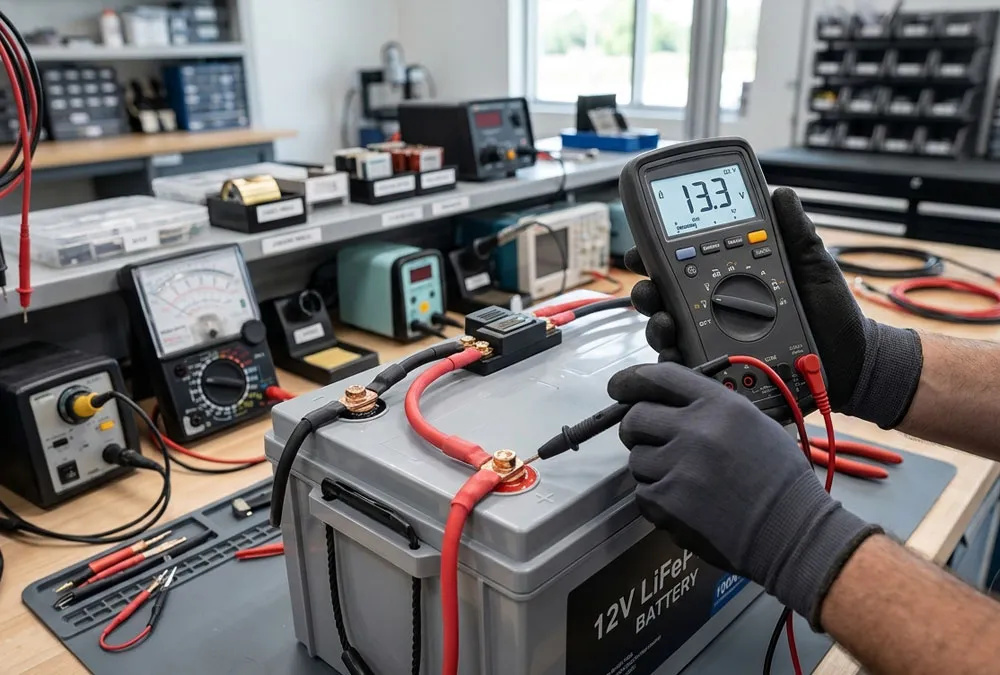
If you’ve ever stood in a golf cart service bay or managed an AGV fleet in a warehouse, you know the headache of a battery dropping power out of nowhere. You check the display, see a steady number, and assume you’re safe—until the equipment halts under a heavy load. Reading a LiFePO4 voltage chart isn’t just about matching numbers on a screen; it’s about understanding how lithium iron phosphate holds its energy differently than legacy lead-acid systems. Whether you run commercial golf carts, industrial floor scrubbers, tuk-tuks, or stationary solar banks, relying on standard voltage readings can trick even seasoned mechanics. A LiFePO4 voltage chart helps users understand the relationship between battery voltage, state of charge (SOC), charging status, and long-term battery health.
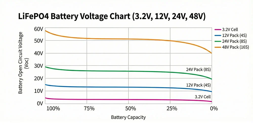
Unlike lead-acid batteries that show a steep, steady drop in voltage as they discharge, lithium iron phosphate maintains a remarkably flat voltage curve. This flat discharge profile provides stable motor torque and consistent performance, but it makes capacity tracking tricky. To accurately estimate capacity, you must combine voltage data with several operational factors:
- SOC (State of Charge): Understanding resting open-circuit values versus active operating numbers.
- Load condition: Accounting for real-time voltage sag during high-amp draws.
- Temperature: Factoring in internal resistance changes in cold or hot environments.
- BMS data: Utilizing integrated coulomb counting for precise monitoring.
LiFePO4 Voltage Chart: Understanding Lithium Iron Phosphate Battery Voltage Basics
To diagnose pack performance or select power supplies, you need to look past high-level battery labels and focus on individual cell chemistry. Raw cell behavior dictates how the entire pack handles daily field cycles.
What Is the Nominal Voltage of a LiFePO4 Battery?
Every individual LiFePO4 cell carries a nominal rating of 3.2V. When built into larger industrial packs, these cells are wired in series (S) to meet higher equipment voltage demands. The table below breaks down common pack builds across commercial applications, along with user benefits for each setup.
| Battery Type | Cell Configuration | Nominal Voltage | Working Voltage Range | User Operational & Financial Advantage |
|---|---|---|---|---|
| 12V LiFePO4 | 4S (4 Cells) | 12.8V | 10.0V – 14.6V | Direct drop-in replacement for 12V lead-acid; eliminates maintenance and acid corrosion. |
| 24V LiFePO4 | 8S (8 Cells) | 25.6V | 20.0V – 29.2V | Provides steady current for floor sweepers and AGVs, doubling runtimes per charge. |
| 36V LiFePO4 | 12S (12 Cells) | 38.4V | 30.0V – 43.8V | Maintains consistent motor speed in commercial utility vehicles under heavy cargo loads. |
| 48V LiFePO4 | 16S (16 Cells) | 51.2V | 40.0V – 58.4V | Delivers maximum power efficiency for golf carts and forklifts with minimal heat loss. |
| 60V LiFePO4 | 20S (20 Cells) | 64.0V | 50.0V – 73.0V | Ideal for high-torque electric three-wheelers and delivery tuk-tuks facing steep inclines. |
| 72V LiFePO4 | 24S (24 Cells) | 76.8V | 60.0V – 87.6V | Powers high-speed commercial mobility and heavy transport carts over long shifts. |
A common misstep among fleet buyers is assuming a 48V battery rests continuously at 48V. In practice, a 16S 48V system operates within a wide window from 40V when empty up to 58.4V during active charging. Understanding this full lithium iron phosphate battery voltage range prevents premature equipment shutoffs.
Buyer Pain Point & Immediate Solution: Field technicians often report that new 48V packs shut down unexpectedly even when meters read “48V.” Solution: Realize that 48V (or 51.2V nominal) sits right near the 15% SOC drop-off knee. Reconfigure low-voltage disconnects on your vehicle controllers to 44V–46V to utilize remaining energy safely without abrupt cutoffs.
Why Do We Need a LiFePO4 Voltage Chart?
Relying on old habits from lead-acid setups causes confusion when managing lithium fleets. A dedicated reference chart allows operators to:
- Accurately determine real remaining capacity during maintenance checks.
- Verify if chargers are supplying correct LiFePO4 charging voltage levels.
- Identify failing or imbalanced cells before a complete pack failure occurs.
- Avoid unnecessary BMS over-voltage or under-voltage protection trips.
- Extend overall cycle life past 3,500 full depth-of-discharge cycles.
Whether managing fleet golf carts, RV house systems, industrial AGVs, solar banks, or light EVs, using an accurate reference guide protects your equipment investment.
LiFePO4 Voltage Chart and State of Charge (SOC): Understanding Battery Capacity
Tracking capacity requires mastering the connection between open-circuit voltage measurements and internal chemistry states.
What Is SOC (State of Charge) in LiFePO4 Batteries?
State of Charge (SOC) measures remaining energy as a percentage of total rated capacity. A reading of 100% SOC indicates a fully saturated pack ready for service. A reading of 20% SOC signals that the battery should be connected to a charger soon to avoid reaching the BMS cut-off line.
Relationship Between LiFePO4 Voltage and SOC
The defining trait of lithium iron phosphate chemistry is its flat voltage plateau. Between 20% SOC and 90% SOC, cell voltage shifts by only a few hundredths of a volt. While this delivers consistent power output to electric motors, it makes simple voltage meters unreliable for fine capacity tracking.
LiFePO4 Battery Charging Stages and SOC
Charging follows a controlled two-stage profile designed to maximize capacity without overheating the pack:
- Stage 1: Constant Current (CC): The charger supplies maximum steady amperage while battery voltage rises rapidly toward its target limit. This stage restores roughly 80% to 85% of total energy.
- Stage 2: Constant Voltage (CV): Voltage locks at the upper threshold (such as 3.65V per cell) while amperage gradually tapers down toward zero, fully saturating the chemistry.
- Stage 3: Charge Termination: Power cuts automatically once current drops below a preset threshold (typically 0.05C), letting the internal BMS handle final cell balancing.
12V LiFePO4 Voltage Chart and Charging Parameters
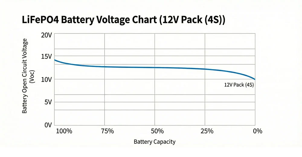
12V setups remain the standard choice for marine vessels, RV house power, small solar arrays, and auxiliary backup banks.
12V LiFePO4 Battery Voltage Chart
The numbers below reflect open-circuit resting voltages measured after the battery has rested for at least 30 minutes with no active load or charge input.
| State of Charge (SOC) | 4S Cell Voltage | 12V Pack Resting Voltage | 12V Pack Charging Voltage | User Experience Advantage |
|---|---|---|---|---|
| 100% (Full) | 3.65V | 13.6V – 14.4V | 14.6V | Maximum energy reserve available for extended off-grid runtimes. |
| 90% | 3.35V | 13.4V | 13.8V | High working voltage; ideal operating range for auxiliary loads. |
| 70% | 3.32V | 13.3V | 13.5V | Maintains strong current output for water pumps and lighting. |
| 50% | 3.30V | 13.2V | 13.4V | Flat plateau midpoint; equipment experiences zero speed degradation. |
| 20% | 3.20V | 12.8V | 13.0V | Low charge warning threshold; schedule recharge to protect cells. |
| 0% (Empty) | 2.50V | 10.0V – 12.0V | N/A | BMS disconnects output to prevent irreversible cathode damage. |
12V LiFePO4 Battery Applications
These compact systems suit low-amperage applications that require high cycle life without heavy maintenance:
- RV house power systems and auxiliary camper van electrics.
- Marine trolling motors and on-board electronics.
- Off-grid residential solar energy storage banks.
- Emergency back-up power for telecom nodes.
12V LiFePO4 Battery Charging Parameters
| Parameter | Recommended Technical Value | User Protection Benefit |
|---|---|---|
| Nominal Voltage | 12.8V | Matches legacy 12V electrical infrastructure directly. |
| Full Charge Voltage | 14.6V (3.65V per cell) | Ensures full 100% saturation without triggering BMS trips. |
| Recommended Charger | 14.6V Dedicated CC/CV Charger | Prevents electrolyte breakdown caused by lead-acid float modes. |
| Charging Current Rate | 0.2C to 0.5C (20A–50A for 100Ah pack) | Balances fast recharge speeds with low internal thermal buildup. |
24V LiFePO4 Voltage Chart and Charging Parameters
24V systems offer higher electrical efficiency for commercial floor sweepers, small material handlers, and mid-sized solar arrays.
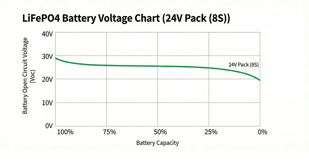
24V LiFePO4 Battery Voltage Chart
| State of Charge (SOC) | 8S Cell Voltage | 24V Pack Resting Voltage | 24V Pack Charging Voltage | Operational Advantage |
|---|---|---|---|---|
| 100% | 3.65V | 27.2V – 28.8V | 29.2V | Delivers full shift coverage for commercial cleaning machines. |
| 80% | 3.34V | 26.7V | 27.6V | Sustains steady brush motor speed on tough floor surfaces. |
| 50% | 3.30V | 26.4V | 26.8V | Stable midway power; zero voltage sag under standard loads. |
| 20% | 3.20V | 25.6V | 26.0V | Signals equipment to return to charging docks soon. |
| 0% | 2.50V | 20.0V – 24.0V | N/A | Automatic BMS cutout prevents total cell exhaustion. |
24V LiFePO4 Battery Applications
Moving from 12V up to 24V cuts current draw in half for the same wattage output, reducing cable size requirements in:
- Automated guided vehicles (AGVs) in light assembly plants.
- Industrial walk-behind and ride-on floor cleaning scrubbers.
- Small electric tuggers and warehouse tow tractors.
24V LiFePO4 Charging Parameters
To keep 24V fleets running smoothly, set charger limits to 29.2V maximum constant voltage. Choose units equipped with internal thermal sensors to slow current if ambient temperatures rise in factory settings.
48V LiFePO4 Voltage Chart and Charging Parameters
A reference 48V LiFePO4 battery voltage chart serves as an essential tool for material handling teams, golf resort managers, and commercial solar operators using 16S configurations.
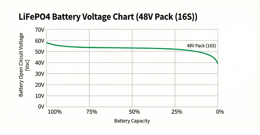
48V LiFePO4 Battery Voltage Chart
| State of Charge (SOC) | 16S Cell Voltage | 48V Pack Resting Voltage | 48V Pack Charging Voltage | Commercial Fleet Advantage |
|---|---|---|---|---|
| 100% | 3.65V | 54.4V – 57.6V | 58.4V | Unlocks full torque and max range for golf carts and AGVs. |
| 80% | 3.34V | 53.4V | 55.2V | Supports continuous heavy lifting in forklift applications. |
| 50% | 3.30V | 52.8V | 53.6V | Consistently maintains drive speed on steep outdoor ramps. |
| 20% | 3.20V | 51.2V | 52.0V | Recharge prompt threshold to avoid mid-shift equipment stalls. |
| 0% | 2.50V | 40.0V – 48.0V | N/A | BMS cuts circuit to stop permanent cell capacity degradation. |
Using a detailed 48V LiFePO4 battery voltage chart with SOC data helps maintenance crews spot weak cells early. This keeps overall operational costs low across large fleets.
48V LiFePO4 Battery Applications
The 48V (51.2V nominal) architecture serves as the industry standard across several commercial sectors:
- Golf Carts & Resort Shuttles: Replaces heavy 6V/8V lead-acid batteries, shedding over 300 lbs to boost speed and climbing power.
- AGVs & Warehouse Forklifts: Supports rapid opportunity charging during shift breaks without memory effects.
- Solar ESS Installations: Matches standard 48V telecom and off-grid inverter inputs directly.
48V LiFePO4 Charging Parameters
| Parameter | Technical Target | Fleet Impact |
|---|---|---|
| Nominal System Voltage | 51.2V | Reduces heat generation across motor controllers and harnesses. |
| Full Charge Threshold | 58.4V | Achieves 100% capacity saturation reliably across all 16 cells. |
| Recommended Charger Output | 58.4V Dedicated Charger | Avoids premature high-voltage cutoffs during charging cycles. |
| Typical Pack Capacities | 50Ah to 300Ah+ | Offers scalable runtimes tailored to daily vehicle duty cycles. |
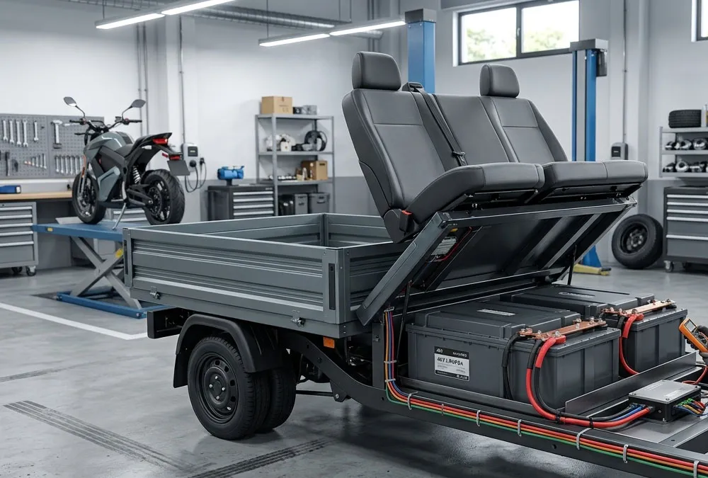
60V LiFePO4 Voltage Chart and Charging Parameters
A 20S 60V (64.0V nominal) battery system delivers high energy density for urban light electric vehicles and multi-passenger transport carts.
60V LiFePO4 Battery Voltage Chart
A fully charged 60V pack reaches 73.0V under active charging, settling to an open-circuit resting voltage around 68.0V. At 50% SOC, resting voltage sits near 66.0V, dropping down to a 50.0V BMS cut-off line when fully empty.
60V LiFePO4 Battery Applications
The 60V architecture powers heavy duty mobility applications across urban transit sectors:
- Electric cargo motorcycles and last-mile delivery fleets.
- Passenger three-wheelers and urban tuk-tuks.
- Commercial utility transport buggies facing steep grades.
60V LiFePO4 Charging Parameters
Pair 60V packs with chargers set to 73.0V DC output. Match current output to pack capacity (e.g., a 30A charger for a 60Ah battery) to complete full recharges in under two hours without triggering thermal cutoffs.
72V LiFePO4 Voltage Chart and Charging Parameters
High-power 24S 72V (76.8V nominal) battery systems meet the high current demands of fast commercial vehicles and heavy industrial movers.
72V LiFePO4 Battery Voltage Chart
| State of Charge (SOC) | 24S Cell Voltage | 72V Pack Resting Voltage | 72V Pack Charging Voltage | High-Power Performance Benefit |
|---|---|---|---|---|
| 100% | 3.65V | 81.6V – 86.4V | 87.6V | Delivers maximum speed and acceleration for urban EVs. |
| 80% | 3.34V | 80.1V | 82.8V | Maintains consistent hill-climbing power on steep terrain. |
| 50% | 3.30V | 79.2V | 80.4V | Provides smooth throttle response throughout long work shifts. |
| 20% | 3.20V | 76.8V | 78.0V | Indicates low power status; return to fleet charging station. |
| 0% | 2.50V | 60.0V – 72.0V | N/A | Prevents cell damage caused by deep over-discharge events. |
Knowing your full 72V LiFePO4 battery voltage range ensures high-speed equipment operates safely without risking low-voltage cutoffs during peak acceleration.
72V LiFePO4 Battery Applications
- High-speed passenger shuttles and resort transport buses.
- Heavy-duty industrial tow tractors and airport baggage carts.
- High-performance electric delivery trucks and utility platforms.
72V LiFePO4 Charging Parameters
Charging a 24S 72V pack requires a constant 87.6V output. Use CANbus-enabled chargers to sync power levels with the BMS in real time, protecting cells during rapid recharge cycles.
Different Types of LiFePO4 Voltage Readings Explained
A common point of confusion for field operators is why battery voltage changes depending on current flow. Measuring techniques change numbers significantly.
Resting Voltage (Open Circuit Voltage)
Open Circuit Voltage (OCV) measures terminal voltage when no loads or chargers are connected. To record accurate resting numbers, let the pack sit for at least 30 to 60 minutes. OCV provides the reliable baseline needed for manual SOC estimation.
Loaded Voltage
Loaded voltage reflects real-time readings taken while the motor or equipment draws power. Current draw creates an immediate voltage drop due to internal cell resistance (IR):
Loaded Voltage = Resting OCV − (Discharge Current × Internal Resistance)
Under heavy acceleration, a 48V pack at 80% capacity may temporarily drop from 53.4V down to 49.0V. This voltage sag is normal and recovers once the throttle is released.
Charging Voltage
Charging voltage represents the potential applied by the power supply to push current back into the cells. This reading reflects charger output rather than true battery energy state. Checking voltage while connected to an active charger will not give an accurate capacity measurement.
LiFePO4 Battery Charging and Discharging Voltage Characteristics
According to technical findings in the 2025 Global Industrial Fleet Electrification Benchmark Report, improper charge cut-off settings account for over 31% of premature BMS service calls in commercial equipment. Understanding voltage limits prevents these unnecessary service disruptions.
How Charging Voltage Affects Battery Performance
Setting charging voltage too high (above 3.65V per cell) stresses cathode structures and triggers high-voltage BMS isolation. Conversely, setting charger output too low (below 3.40V per cell) leaves cells partially empty, reducing overall equipment operating hours.
How Discharge Voltage Affects Battery Performance
Allowing cell voltage to drop below 2.0V causes irreversible copper plating on anode collectors, creating internal short circuits. A well-configured BMS prevents this by isolating the circuit when cells drop to 2.5V.
How to Estimate LiFePO4 SOC Using Voltage Chart
Follow these steps to estimate remaining battery capacity during routine maintenance:
Step 1: Measure Resting Voltage
Turn off the vehicle or equipment completely. Disconnect chargers, turn off keyswitches, and let the battery sit idle for 30 to 45 minutes to let internal cell chemistry stabilize.
Step 2: Compare Voltage With SOC Chart
Take a reading across main terminals using a digital multimeter. Compare that value against your specific system chart. For example, a resting reading of 52.8V on a 16S 48V battery indicates roughly 50% SOC.
Limitations of Using Voltage Alone
Because the discharge curve remains flat between 30% and 80% SOC, small digital meter inaccuracies can shift capacity estimates by 30% or more. For accurate, real-time tracking, install smart shunt monitors or BMS units that utilize active coulomb counting.
Temperature Effects on LiFePO4 Voltage Readings
Operating temperatures alter internal battery resistance, directly impacting terminal voltage readings in extreme working environments.
How Low Temperature Affects Charging Voltage
Cold conditions below 0°C increase internal cell resistance. This causes terminal voltage to spike quickly during charging, potentially triggering false high-voltage BMS cutoffs before the pack actually fills. Never charge lithium iron phosphate cells below freezing unless equipped with internal heating elements, as forcing current into frozen cells causes permanent lithium plating.
How High Temperature Affects Battery Performance
Heat above 45°C lowers internal resistance, causing loaded voltages to appear slightly higher while accelerating chemical degradation. Operating in extreme heat shortens overall cycle life if charging currents are not adjusted downward.
How to Diagnose Abnormal LiFePO4 Battery Voltage Problems
Use this diagnostic guide to troubleshoot common field voltage issues quickly:
Battery Voltage Too Low
- Symptom: Terminal reading shows 0V or falls below low cut-off limits.
- Cause: BMS activated low-voltage protection due to over-discharge, or an internal cell dropped below minimum limits.
- Fix: Apply a specialized lithium charger with low-voltage recovery function to wake up the BMS gently.
Battery Voltage Too High
- Symptom: Charger trips error lights, or BMS disconnects power during charging cycles.
- Cause: Charger output voltage is set too high, or a single imbalanced cell spiked above 3.65V early.
- Fix: Verify charger output calibration, and run a slow balance charge to equalize individual cell voltages.
Uneven Cell Voltage
- Symptom: Pack capacity drops suddenly despite total voltage looking normal.
- Cause: Passive balancing failed to keep series cells aligned over multiple deep discharge cycles.
- Fix: Connect an active cell balancer or run a prolonged low-current saturation charge cycle to align all cells.
Three Methods to Check LiFePO4 Battery Capacity and Health
Choose the diagnostic method that best fits your tools and operational requirements:
Method 1: Measuring Open Circuit Voltage With a Multimeter
A quick, low-cost approach for spot-checking pack status during field calls. Ensure the battery rests idle before taking readings.
Method 2: Using a Battery Monitor
Installing a shunt-based capacity monitor tracks current flowing in and out of the battery in real time. This delivers accurate coulomb-counting SOC readings directly to equipment dashboards.
Method 3: Using Solar Charge Controller Data
Solar energy systems provide live voltage and current logs through MPPT controller interfaces. Use historical trend logs to assess pack health and track long-term capacity retention.
Choosing the Right LiFePO4 Battery System for Your Application
Selecting the right battery system requires matching operational duty cycles with accurate system voltages.
Golf Cart and Utility Vehicle Applications
Upgrading golf carts to 48V (51.2V nominal) LiFePO4 packs cuts weight, eliminates water top-offs, and delivers consistent speed uphill throughout the entire round.
AGV and Industrial Equipment Applications
Industrial AGVs and material handling fleets benefit from 24V or 48V setups that support fast opportunity charging during scheduled operator breaks.
Electric Motorcycle and Three-Wheel Vehicle Applications
Urban transport fleets and delivery tuk-tuks require 60V or 72V packs to achieve high motor torque, rapid acceleration, and steady performance under heavy cargo payloads.
Solar Energy Storage Applications
Off-grid homes and commercial energy installations rely on 48V LiFePO4 banks for high round-trip efficiency and seamless integration with modern hybrid inverters.
ENERGYSPLENDOR LiFePO4 Battery Solutions
Building high-performance commercial equipment requires reliable, long-lasting power systems. ENERGYSPLENDOR manufactures industrial-grade LiFePO4 battery solutions built to withstand demanding operating environments.
Custom LiFePO4 Battery Systems From 12V to 72V
We design and build complete custom battery systems across all standard voltages—including 12V, 24V, 36V, 48V, 60V, and 72V configurations—tailored to meet your exact dimensional and electrical needs.
Battery Solutions for Golf Cart, AGV and Energy Storage
Our engineered packs feature integrated smart BMS units, rugged vibration-resistant enclosures, CANbus communication options, and precision-matched chargers designed for maximum service life.
OEM/ODM Battery Pack Manufacturing Capability
From prototype testing through to full fleet production, ENERGYSPLENDOR provides complete engineering support, custom wiring harnesses, and custom software integration for commercial manufacturers worldwide.
Frequently Asked Questions
What voltage should a fully charged LiFePO4 battery be?
A fully charged LiFePO4 cell reaches 3.65V during charging, settling to an open-circuit resting voltage around 3.40V–3.45V per cell (e.g., 13.6V for 12V packs, 54.4V for 48V packs).
What is the voltage range of a 48V LiFePO4 battery?
A standard 16S 48V (51.2V nominal) pack operates between a lower 40.0V cutoff limit up to a maximum 58.4V charging ceiling.
How do I read a LiFePO4 battery voltage chart?
Measure resting voltage when no loads are connected. Match that value against your pack’s series cell configuration on the chart to read estimated state of charge percentage.
Can voltage accurately show LiFePO4 battery capacity?
Resting voltage gives a useful rough estimate at the empty and full ends of the range. However, because the middle voltage plateau is very flat, using a coulomb-counting shunt monitor provides much higher accuracy.
What is the difference between LiFePO4 charging voltage and nominal voltage?
Nominal voltage represents the flat working baseline during discharge (3.2V/cell), whereas charging voltage is the higher potential (3.65V/cell) required from a power supply to drive energy back into the pack.
Related Posts
 https://anengjibattery.com/wp-content/uploads/2026/09/AnengJIBattery-Best-LiFePO4-Battery-How-to-Choose-the-Right-One.webp
675
1000
Battery Expert Team
https://anengjibattery.com/wp-content/uploads/2025/06/logo2-300x138.png
Battery Expert Team2026-09-17 08:52:142026-09-17 08:52:31How to Choose the Best LiFePO4 Battery
https://anengjibattery.com/wp-content/uploads/2026/09/AnengJIBattery-Best-LiFePO4-Battery-How-to-Choose-the-Right-One.webp
675
1000
Battery Expert Team
https://anengjibattery.com/wp-content/uploads/2025/06/logo2-300x138.png
Battery Expert Team2026-09-17 08:52:142026-09-17 08:52:31How to Choose the Best LiFePO4 Battery https://anengjibattery.com/wp-content/uploads/2026/09/anengjiBattery-lifepo4-battery-cell-packaging-wholesale.webp
675
1000
Battery Expert Team
https://anengjibattery.com/wp-content/uploads/2025/06/logo2-300x138.png
Battery Expert Team2026-09-16 09:52:342026-09-16 09:52:57LiFePO4 Battery Wholesale Guide: Best Suppliers in Spain
https://anengjibattery.com/wp-content/uploads/2026/09/anengjiBattery-lifepo4-battery-cell-packaging-wholesale.webp
675
1000
Battery Expert Team
https://anengjibattery.com/wp-content/uploads/2025/06/logo2-300x138.png
Battery Expert Team2026-09-16 09:52:342026-09-16 09:52:57LiFePO4 Battery Wholesale Guide: Best Suppliers in Spain https://anengjibattery.com/wp-content/uploads/2026/09/anengjibattery-Top-Lithium-Ion-Battery-Producers-for-Spain-Market-Growth.webp
675
1000
Battery Expert Team
https://anengjibattery.com/wp-content/uploads/2025/06/logo2-300x138.png
Battery Expert Team2026-09-16 01:13:392026-09-16 01:14:05Top Lithium Ion Battery Producers for Spain’s Market Growth
https://anengjibattery.com/wp-content/uploads/2026/09/anengjibattery-Top-Lithium-Ion-Battery-Producers-for-Spain-Market-Growth.webp
675
1000
Battery Expert Team
https://anengjibattery.com/wp-content/uploads/2025/06/logo2-300x138.png
Battery Expert Team2026-09-16 01:13:392026-09-16 01:14:05Top Lithium Ion Battery Producers for Spain’s Market Growth https://anengjibattery.com/wp-content/uploads/2026/09/Bulk-Lithium-Ion-Battery-Cells-Procurement-Guide-B2B-Sourcing.webp
675
1000
Battery Expert Team
https://anengjibattery.com/wp-content/uploads/2025/06/logo2-300x138.png
Battery Expert Team2026-09-14 09:47:322026-09-14 09:47:48Bulk Lithium-Ion Battery Cells Procurement Guide | B2B Sourcing
https://anengjibattery.com/wp-content/uploads/2026/09/Bulk-Lithium-Ion-Battery-Cells-Procurement-Guide-B2B-Sourcing.webp
675
1000
Battery Expert Team
https://anengjibattery.com/wp-content/uploads/2025/06/logo2-300x138.png
Battery Expert Team2026-09-14 09:47:322026-09-14 09:47:48Bulk Lithium-Ion Battery Cells Procurement Guide | B2B Sourcing


Leave a Reply
Want to join the discussion?Feel free to contribute!